Removal And Installation: Installation
NOTE:
Quadrifoglio model shown in illustration base model similar.
NOTE:
Removal and installation process is the same for both sides of the vehicle.
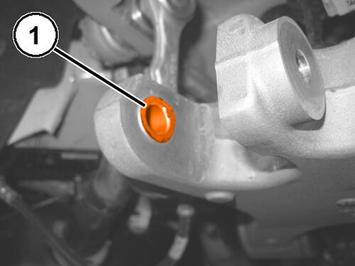
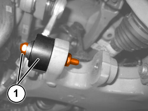
- In order to install the shock absorber into the lower control arm, you will need to push the bushing (1) back into the lower control arm.
- Using an appropriate tool (1) move the bushing back into the lower control arm for more clearance.
- Position the shock absorber in place in the vehicle, and if equipped connect the shock absorber solenoid valve wire harness connector.NOTE:
Carefully feed the shock absorber solenoid valve wire through the hole in the body, and take care not to pinch the wire.
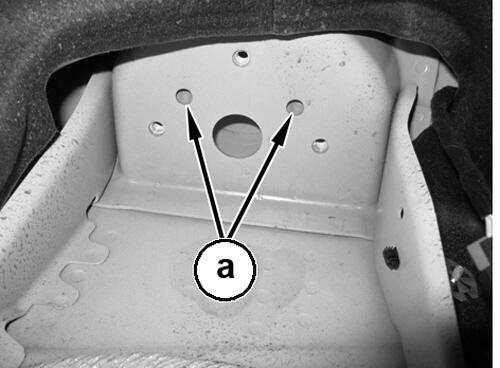
- Position the shock absorber into place against the body, making sure to line up the locating pins with the holes in the body (a).
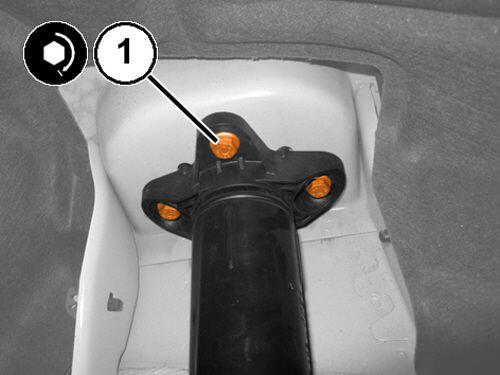
- Install the three shock absorber to body mounting bolts and tighten to the proper specification. Refer to TECHNICAL SPECIFICATIONS .
- If removed reposition the jack under the lower control arm.
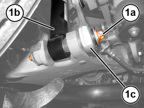
- Install a NEW
shock absorber to lower control arm mounting bolt, Do not tighten at this time.
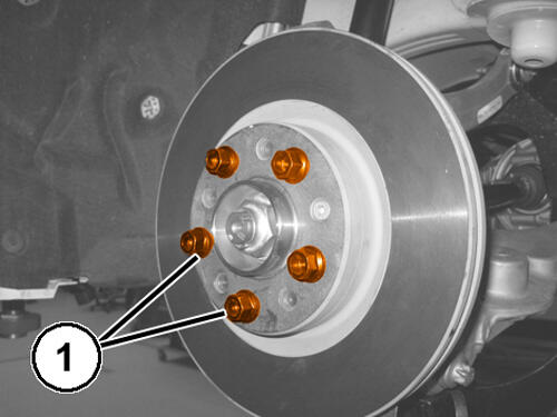
- Install the wheel studs on the hub and bearing without tightening.
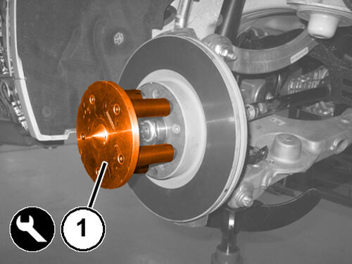
- Mount the special tool (special tool #2000025100, Measuring Tool, Wheel Centering) (1) on the wheel stud heads.
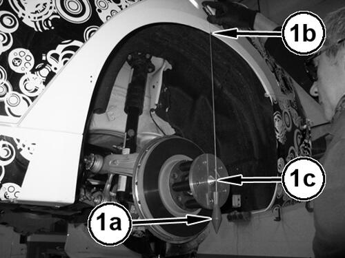
- Using an appropriate plump-bob (2a) determine and mark the stud curvature (2b) that corresponds to the wheel axle (2c).
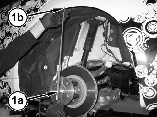
- Lift the lower control arm up until the height 366.5 mm between the wheel center (1a) and the corresponding mark on the wheel arch (1b).
- Tighten the shock absorber to lower control arm mounting bolt to the proper specification. Refer to TECHNICAL SPECIFICATIONS .
- Remove the special tool, Measuring Tool, Wheel Centering 2000025100.
- Remove the jack from the lower control arm.
- Install the tire and wheel assembly. Refer to REMOVAL AND INSTALLATION .
- Connect the negative battery cable.
- Remove the support and lower the vehicle.