Transmission Oil Pump
REMOVAL
- Remove the transmission. Refer to REMOVAL AND INSTALLATION .
- Remove the valve body. Refer to VALVE BODY, REMOVAL AND INSTALLATION .
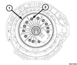
- Remove the 13 transmission oil pump assembly to case bolts (2).
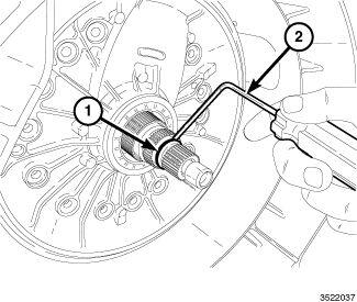
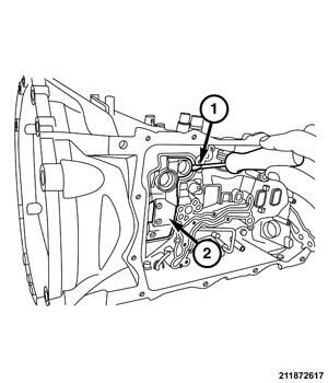
- Remove the input shaft O-ring (1) using a small pick (2) or equivalent.
- Carefully pry the transmission oil pump assembly (1) away from the case (2) with a small flat blade screwdriver or equivalent through the case opening.
- From the front of the transmission, remove the transmission oil pump assembly.NOTE:
Apply air pressure slowly, oil may spray when B-piston releases from the assembly.
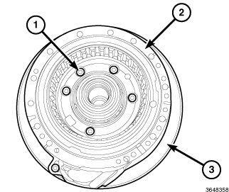
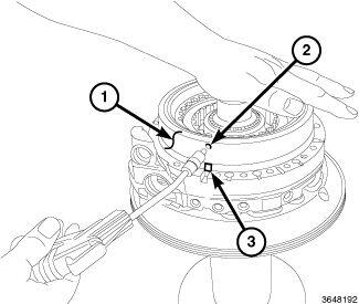
- With one hand above B-piston (1), carefully apply air pressure into the hole directly above the B-piston alignment tab (3) to remove B-piston (2) from the assembly.
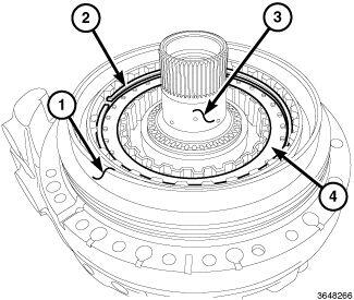
- Remove the outer ring (1) (inside B-piston).
- Remove the snap ring (2).
- Remove the clutches and spacers (4).
- Remove the hub (3).
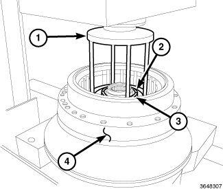
- Position the transmission oil pump housing assembly (4) in a suitable press.
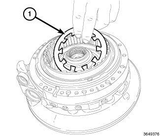
- Using (special tool #8285, Compressor, Spring) (1), press on the fingers of the piston retainer to remove tension on the split retaining ring (2), and remove the two halves of the retaining ring (2).
- Remove the piston retainer and plate (1).
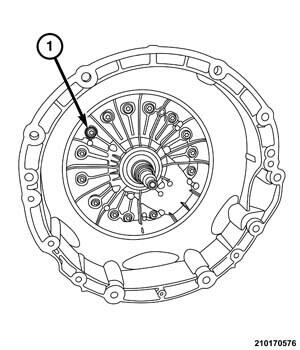
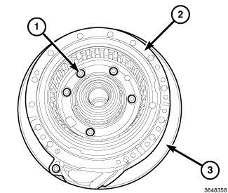
- Remove the five bolts (1) and separate the transmission oil pump housing (2) from the front transmission oil pump cover (3).
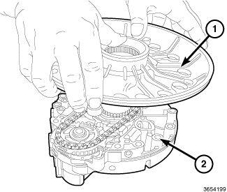
- Separate the front cover (1) from the transmission oil pump housing (2).
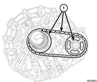
- Remove the drive sprocket, chain and pump body (1) as an assembly.
- Remove and discard all O-rings.
INSTALLATION
NOTE:
If transmission oil pump was disassembled, replace all O-rings.
- Install the drive sprocket, chain and pump body (1) as an assembly into the transmission oil pump housing.
- Set the pump cover (1) onto the transmission oil pump housing (2).NOTE:
The transmission oil pump bolts under the A-clutch must be replaced.
- Install the NEW
six bolts (1) and tighten to 5 N.m (44 in. lbs.) plus 45°.
- Install the piston plate (1) and the piston retainer.
- Position the transmission oil pump housing assembly (4) in a suitable arbor press.
- Using (special tool #8285, Compressor, Spring) (1), press on the fingers of the piston retainer and install the two halves of the retaining ring (2).
- Install the hub (3).
- Install the clutches and spacers (4).
- Install the snap ring (2).
- Install the outer ring (1) (inside B-piston).
- Install the B-piston.NOTE:
Firmly press the transmission oil pump in place hand before drawing it in with bolts.
- Install the 14 NEW
transmission oil pump cover retaining bolts (2) and tighten the transmission oil pump cover as follows:
- In order to seat the transmission oil pump cover properly, pre tighten bolts one, seven and nine to 6 N.m (53 in. lb.).
- Working in a clockwise pattern, beginning with number one, tighten to 10 N.m (89 in. lb.).
- Working in a clockwise pattern, beginning with number one, tighten an additional 90°.
- Install the NEW input shaft O-ring (1).
- Install the valve body. Refer to VALVE BODY, REMOVAL AND INSTALLATION .
- Install the transmission. Refer to REMOVAL AND INSTALLATION .