Removal And Installation
If this valve body with TCM/TCMA is being replaced with a new unit, use a diagnostic scan tool to perform the Flash Programming Procedure (if available).
REMOVAL
The Transmission Control Module (TCM), or Transmission Control Module Assembly (TCMA) is extremely sensitive to Electrostatic Discharge (ESD). Always use a ground strap and follow the ESD guidelines in ELECTROSTATIC DISCHARGE SENSITIVE DEVICES. Failure to follow these instructions may result in damage to the TCM/TCMA.
- Disconnect and isolate the negative battery cable.
- Raise and support the vehicle. Refer to HOISTING, STANDARD PROCEDURE .
- Drain the transmission fluid into a container. Refer to FLUID/FILTER SERVICE
.
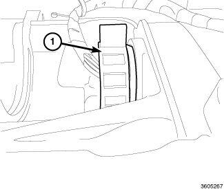
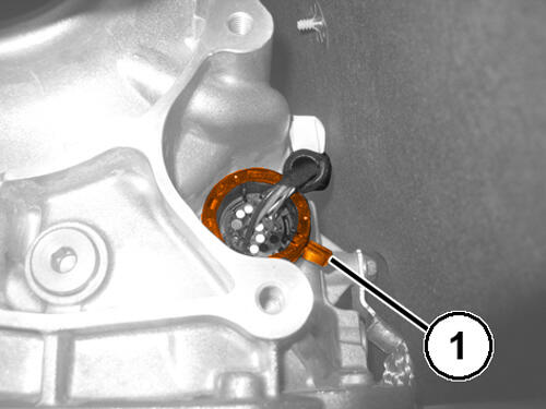
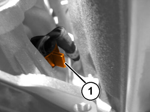
- Disconnect the transmission solenoid wire harness connector by turning the locking mechanism lock (1) of the adapter plug counter-clockwise and slightly pulling the transmission solenoid wire harness connector.NOTE:
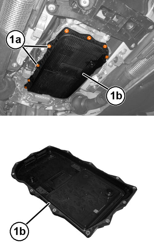
Inspect the gasket (1b) for reuse. If the seal is cut or torn, replace the gasket.
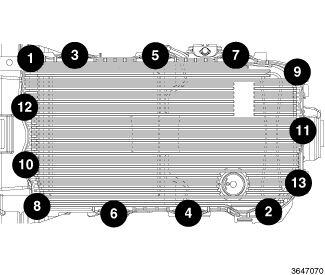
- Remove the thirteen transmission oil pan/filter assembly bolts (1a).
- Carefully detach the transmission oil pan/filter assembly (1b) and gasket.
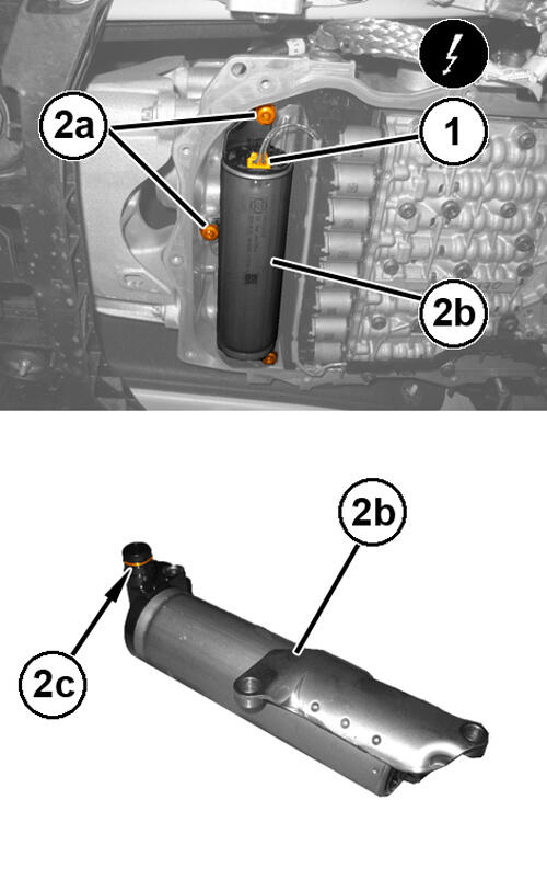
- If equipped, disconnect the Hydraulic Impulse Oil Storage (H.I.S) connector (1).
- If equipped, remove three bolts (2a) and the H.I.S. accumulator (2b).
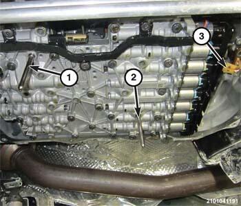
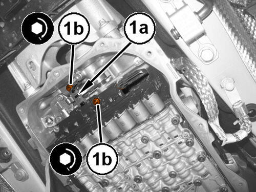
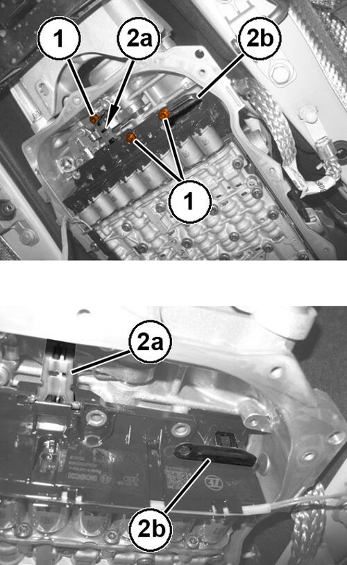
- Remove the valve body assembly end retainer bolts (1).
- Lift the electrical connector lock (2b) to release the internal harness end from inside the transmission for valve body assembly removal.
- Remove the Output Speed Sensor (OSS) bolt (1) and pull the OSS (2a) loose from the case.
- Using (special tool #10377, Remover/Installer, Guide Sleeve) (1) carefully pull the electrical harness insulator (2) straight out from the transmission case (3).
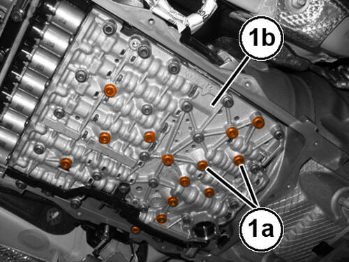
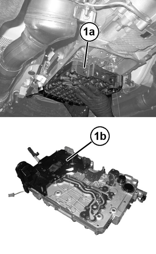
- Remove the valve body assembly (1b) bolts (1a).
- Carefully lower the valve body assembly (1a) from the transmission.NOTE:
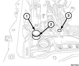
The fluid port may remain in the valve body upon removal, remove and discard the O-rings.
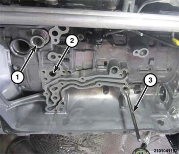
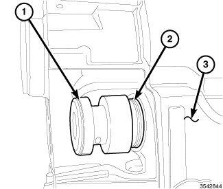
- Remove the fluid transfer port (1) from the transmission.
- Remove and discard the O-ring (2) and seal (3).
INSTALLATION
The Transmission Control Module (TCM), or Transmission Control Module Assembly (TCMA) is extremely sensitive to Electrostatic Discharge (ESD). Always use a ground strap and follow the ESD guidelines in ELECTROSTATIC DISCHARGE SENSITIVE DEVICES. Failure to follow these instructions may result in damage to the TCM/TCMA.
- Install the fluid port (1) with NEW
O-rings (2) and seal (3) to the valve body.
- Install one of the valve body (special tool #10379, Pins, Valve Body Alignment) (3) in the rear of the transmission as shown in illustration as a guide.NOTE:
Make sure the speed sensor at the rear of the valve body does not get caught between the valve body and the transmission case when positioning the valve body to the case.
- Carefully guide the front of the valve body over the cradle while aligning the rear of the valve body with the alignment pin.
- Install the front alignment pin (1).
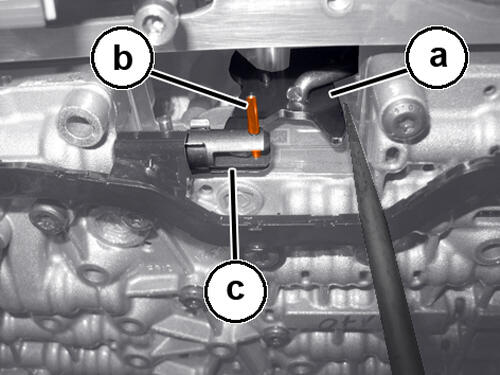
- When installing the valve body assembly, press the park lever (a) to align (b) in the park control solenoid valve (c).
- Use an appropriate tool on one of the alignment pins to assist in holding the valve body in position while installing the remaining fasteners.
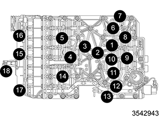
- Install the valve body assembly retaining bolts not including 16-18 and hand tighten.
- Remove the pins and install the remaining bolts.
- Using (special tool #10377, Remover/Installer, Guide Sleeve) (1) carefully install the electrical harness insulator (2) to the transmission case (3).
- Lock the electrical connector lock (2) to the internal harness end.
- Install the OSS (1a) in the case install the OSS bolt (1b) and tighten to the proper. Refer to TORQUE SPECIFICATIONS
.
- If equipped, install the Hydraulic Impulse Oil Storage (H.I.S.) accumulator (2b).
- Tighten the bolts (2a) to the proper. Refer to TORQUE SPECIFICATIONS .
- Connect the H.I.S. electrical connector (1).
- Tighten the valve body fasteners to the proper. Refer to TORQUE SPECIFICATIONS
.
- Install the transmission oil pan/filter assembly and gasket (1b).
- Install the thirteen oil pan retaining bolts and tighten the fasteners to the proper using the sequence given. Refer to TORQUE SPECIFICATIONS
.
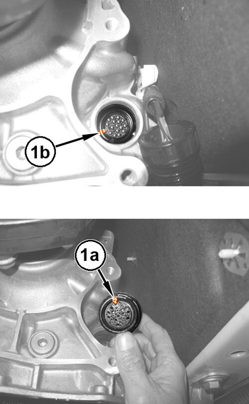
- Install the transmission wire harness connector (1a) back in the transmission case in the correct position (1b).
- Connect the plug connector (1).
- Turn the locking mechanism (1) of the harness plug clockwise and lock in place.
- If the valve body is replaced, program the TCM. Refer to MODULE, TRANSMISSION CONTROL (TCM), MODULE PROGRAMMING .
- Perform the TRANSMISSION FILL AFTER SERVICE procedure. Refer to TRANSMISSION FILL AFTER SERVICE .
- Perform the TRANSMISSION VERIFICATION TEST. Refer to TRANSMISSION VERIFICATION TEST .