Removal And Installation: AWD: Installation
- Position the knuckle into place on the vehicle guiding the half shaft through the hub and bearing.
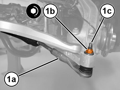
- Install the upper control arm ball joint into the knuckle and install a NEW upper control arm to knuckle pinch bolt, Do not tighten at this time.
- Install the lower control arm ball joint into the knuckle and install a NEW lower control arm to knuckle mounting nut, Do not tighten at this time.
- Install the tension strut ball joint into the knuckle and install a NEW tension strut to knuckle mounting nut, Do not tighten at this time.
- Carefully install the wheel speed sensor into the knuckle and install and tighten the wheel speed sensor to knuckle mounting bolt to the proper specification. Refer to TORQUE SPECIFICATIONS .
- Position the active damping sensor with bracket in place and install the two active damping sensor bracket to knuckle mounting bolts and securely tighten.
- Install the wheel studs in the hub and bearing, Do not tighten.
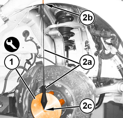
- Mount the special tool (special tool #2000025100, Measuring Tool, Wheel Centering) (1) on the wheel stud heads.
- Using an appropriate plump-bob (2a) determine and mark the stud curvature (2b) that corresponds to the wheel axle (2c).
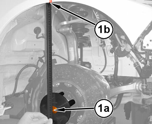
- Position a suitable jack under the knuckle.
- Raise the knuckle up until the height 373.5 mm between the wheel center (1a) and the corresponding mark on the wheel arch (1b) is reached
- Tighten the upper control arm to knuckle pinch bolt to the proper specification. Refer to FRONT, TECHNICAL SPECIFICATIONS .
- Tighten the lower control arm to knuckle mounting nut to the proper specification. Refer to FRONT, TECHNICAL SPECIFICATIONS .
- Tighten the tension strut to knuckle mounting bolt to the proper specification. Refer to FRONT, TECHNICAL SPECIFICATIONS .
- Remove the jack from under the knuckle and remove the special tool and wheel studs from the hub and bearing.
- Install the outer tie rod end to the knuckle and install a NEW
outer tie rod end to knuckle mounting nut and tighten to the proper specification. Refer to TECHNICAL SPECIFICATIONS
.
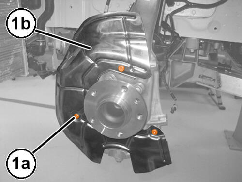
- Position the disc brake guard (1b), and install the three disc brake guard to knuckle mounting bolts (1a) and tighten to the proper specification. Refer to TORQUE SPECIFICATIONS .
- Install the front brake rotor. Refer to ROTOR, BRAKE, REMOVAL AND INSTALLATION
.NOTE:
Always install a new hub nut. The original hub nut is one-time use only and must be discarded when removed.
- Install a NEW
hub nut (1) and while a helper applies the brakes, tighten the nut to the proper specification. Refer to TECHNICAL SPECIFICATIONS
.NOTE:
Do not use air tools on staking tool while staking hub nut.
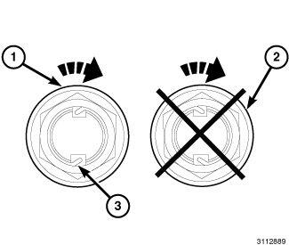
- Using (special tool #10287, Tool, Front Hub Staking)align the leading cutting edge of tool with the channel on axle. Tighten fastener on staking tool with hand tools until the threads bottom out completely.NOTE:
The hub nut must be staked as shown (1) in Correct Hub Nut Staking. Both edges must be split and bent into the shape shown (3). The staking must be in the opposite direction from the forward rotation of the wheel. In illustration.
NOTE:Do not stake the hub nut as shown in Correct Hub Nut Staking (2). In illustration.
- Remove the supports and lower the vehicle.
- Preform a wheel alignment. Refer to WHEEL ALIGNMENT, STANDARD PROCEDURE .