Description And Operation
CRANKCASE OIL VAPOR RECIRCULATION SYSTEM
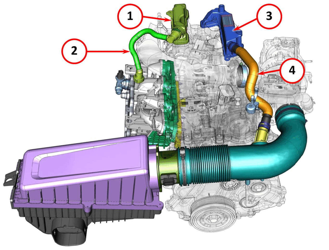
The oil vapor (blow-by) recirculation system directs oil vapors towards air-oil separators, from which the vapors are then sent to the engine air intake system to be burned in the combustion chamber. The system consists of the following components:
- Oil vapor separator for recirculation to the intake manifold
- Vapor recirculation pipe to the intake manifold
- Oil vapor separator for recirculation to the turbocharger air intake
- Vapor recirculation pipe to the turbocharger air intake
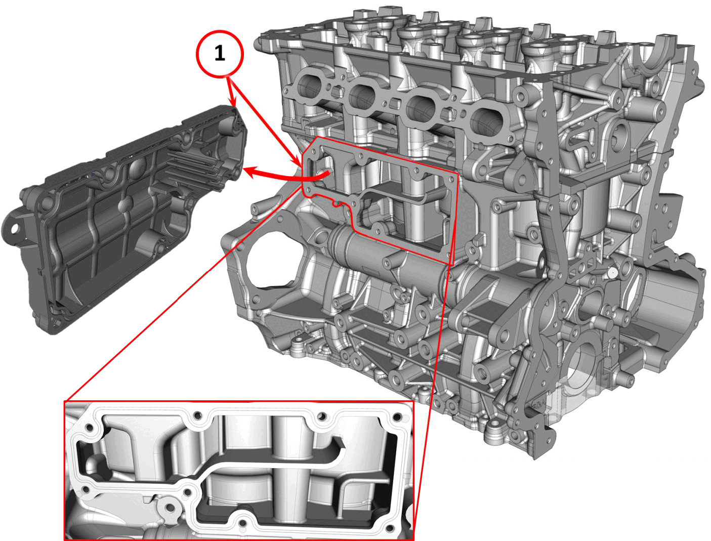
The oil vapor separator is composed of a plastic cover that creates a labyrinth formed in the side surfaces of the engine block. This is the first separation of the vapors that enter the crankcase from the bottom. Further separation of the vapors from the crankcase oil is completed in the separator located on the cylinder head cover (exhaust side).
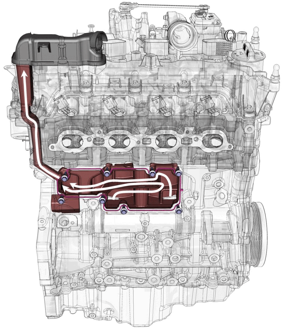
After the vapor flow has been separated from the larger oil particles, channels in the cylinder head direct the flow to the separator on the cylinder head cover.
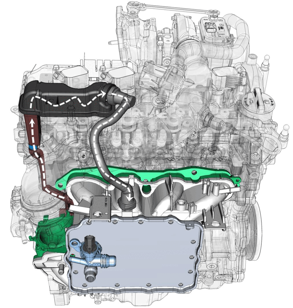
When adequate vacuum is created in the intake manifold, the vapors leave the separator on the cylinder head cover through a flow control valve.
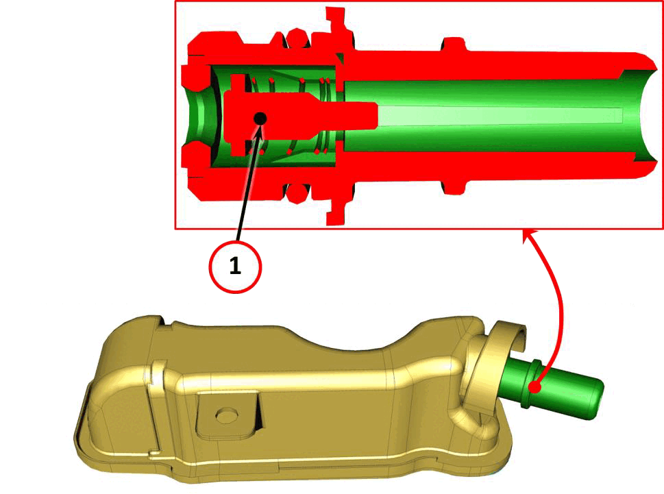
The oil vapor flow control valve regulates the vapor flow and closes if there is a high vacuum in the intake manifold, which would risk sucking up engine oil.
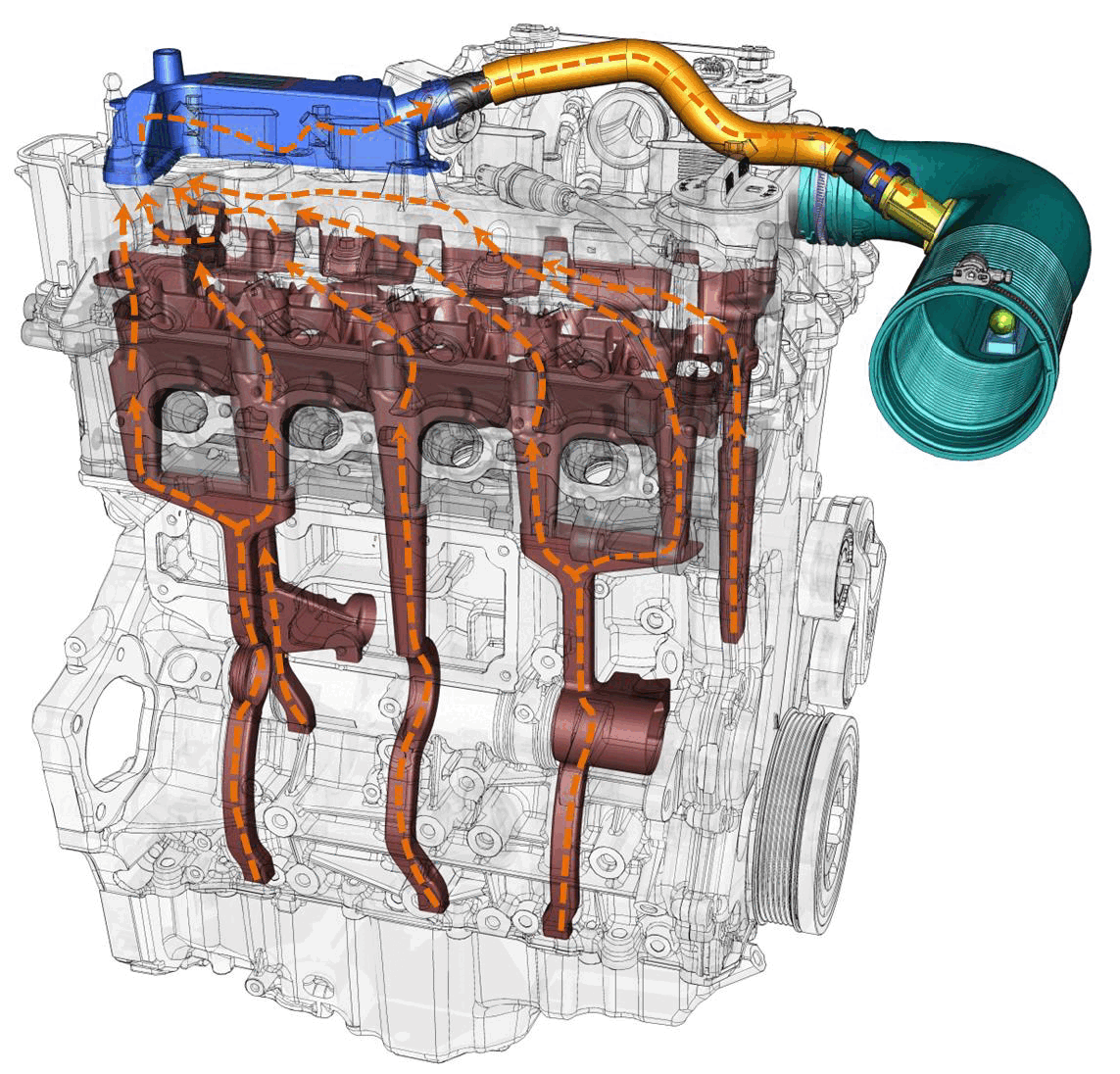
The oil vapors from the oil pan are drawn to the top of the cylinder head by channels in the engine block. The oil vapors enter the separator located on the exhaust side of the cylinder head cover and are then sent to the turbocharger inlet. The oil vapors flow to the intake manifold when the turbocharger has a high vacuum (high engine load).
FUEL VAPOR RECIRCULATION SYSTEM
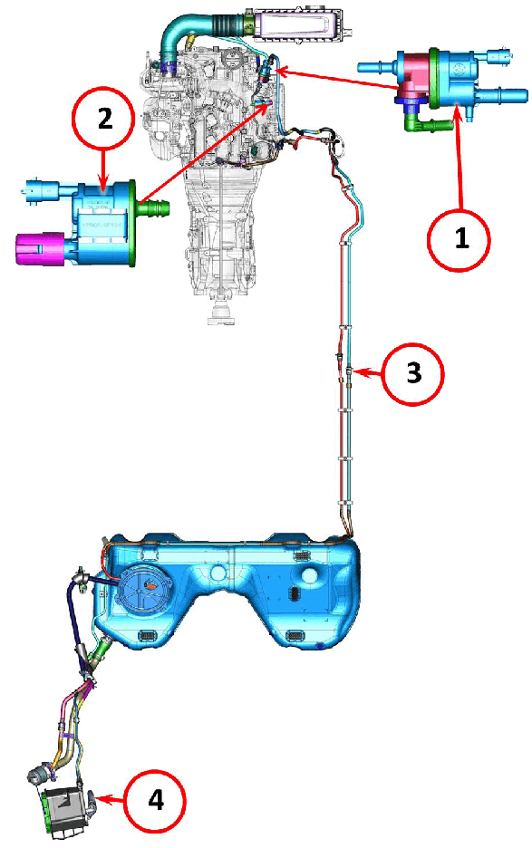
The fuel vapor recirculation system consists of the following components:
- Evaporative emissions purge solenoid
- OBD vent valve
- Fuel vapor supply pipe from the vapor canister to the purge solenoid
- Vapor canister
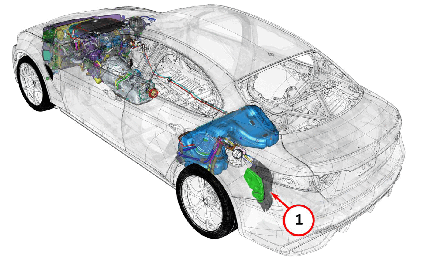
The vapor canister (1) is located behind the left rear wheel arch.
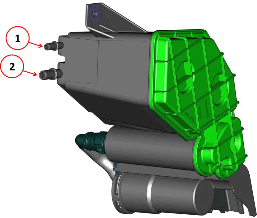
The vapor canister has a fuel vapor inlet (1) from the fuel tank and a fuel vapor outlet (2) to the evaporative emissions purge solenoid.
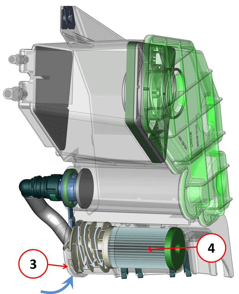
Fuel vapors from the fuel tank enter the vapor canister and move downwards through the canister until they reach the activated charcoal filter (4) where they are deposited. When the evaporative emissions purge solenoid opens (controlled by the PCM), engine intake vacuum causes the vapors to rise up in the opposite direction through the canister where they exit through the fuel vapor outlet as outside air enters the filter through side slits (3).
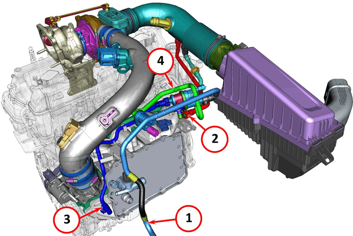
The pipe from the vapor canister (1) is connected to the evaporative emissions purge solenoid inlet. Once the fuel vapors reach the purge solenoid, they can take two paths: to the turbocharger inlet (2) or to the intake manifold (3) (downstream from the throttle body).
A hose (4) connects the vapor canister inlet to the OBD vent valve.
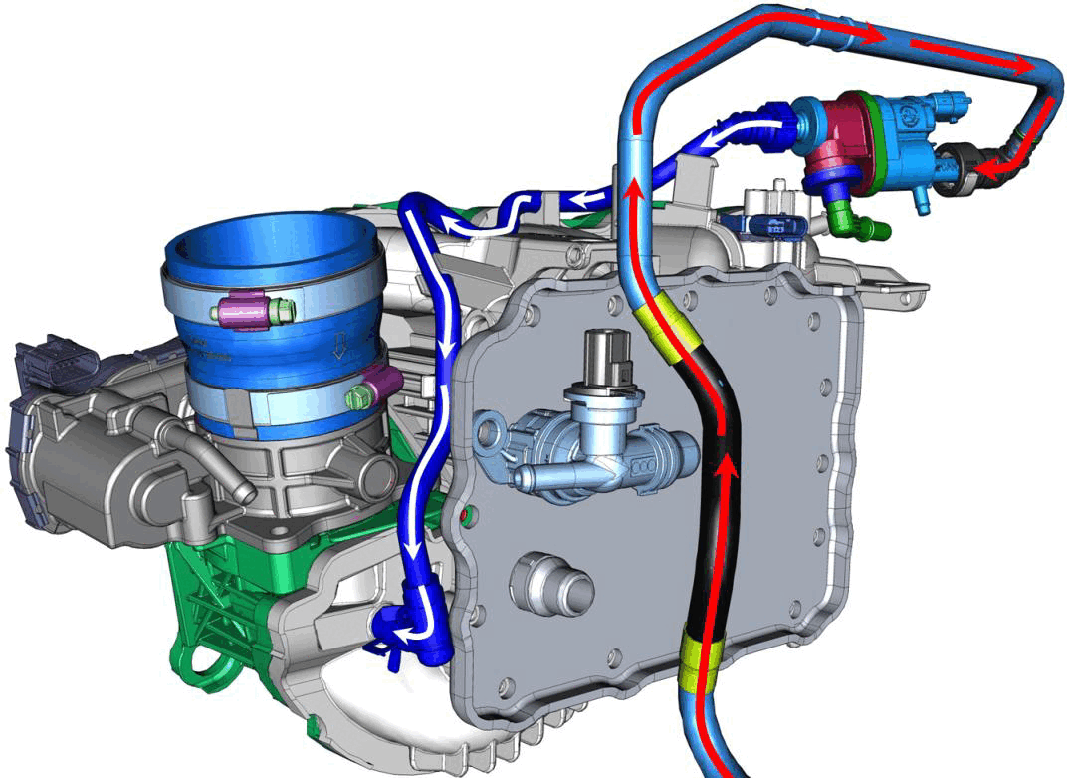
One of the two paths that the fuel vapors can be routed to the engine; to the intake manifold downstream from the throttle body.
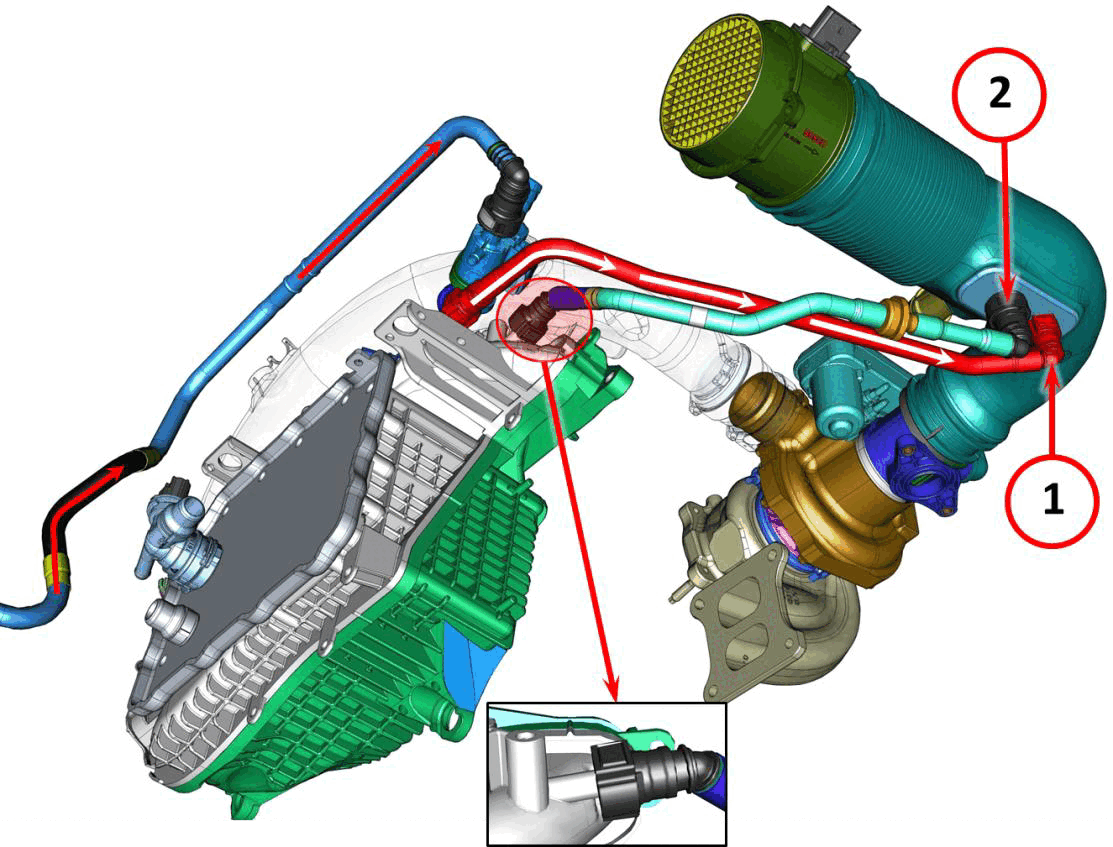
The other path that the fuel vapors can be routed to the engine is possible because of a venturi effect created where the vapor pipe is connected to the turbocharger air inlet hose (1). Pressurized air from the intercooler (2) makes the venturi effect possible.
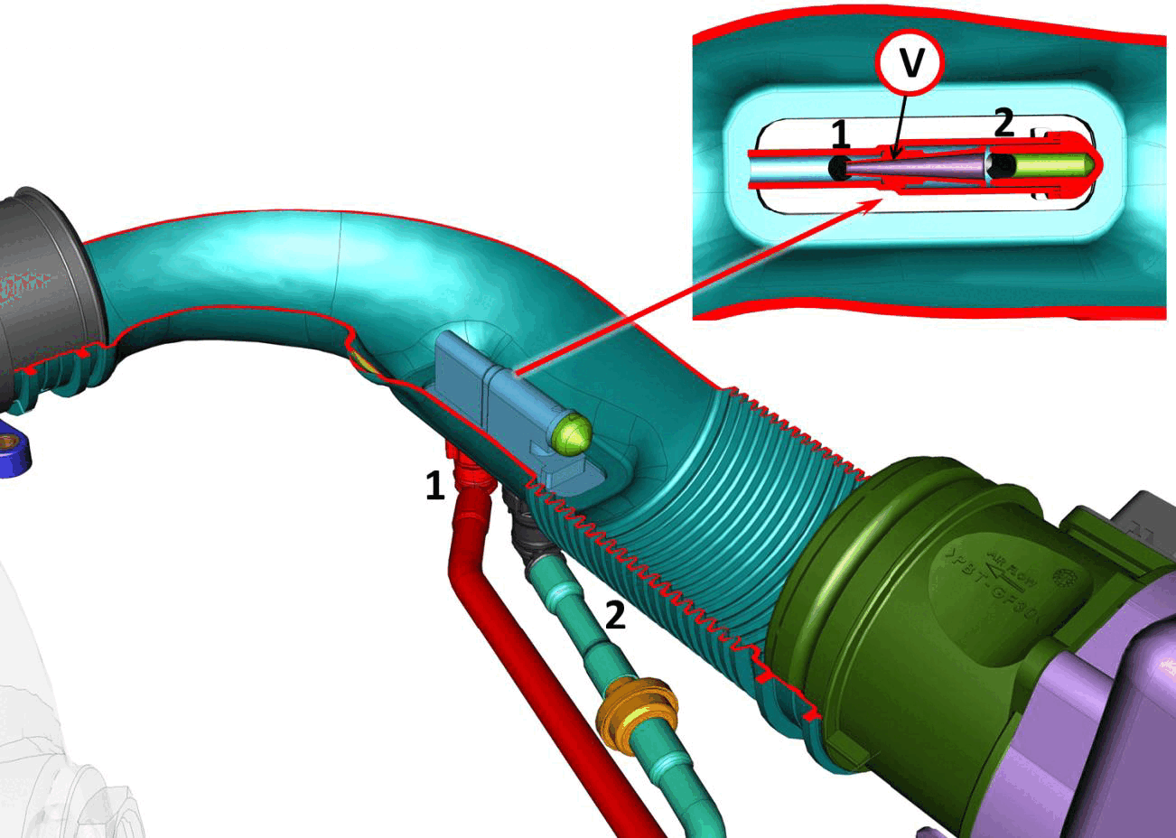
Air under pressure (2) enters from the intercooler. It runs along the "V" channel, creating a venturi effect that draws in the fuel vapors (1).
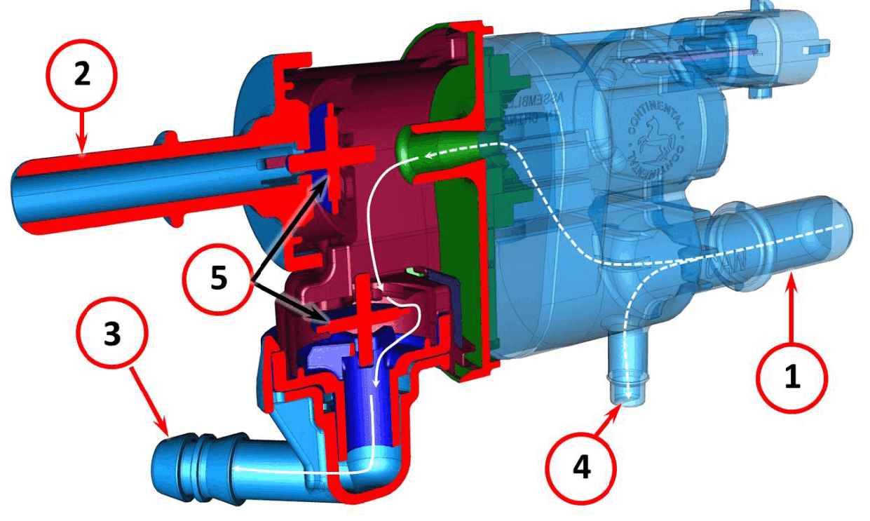
When the evaporative emissions purge valve is commanded open by the PCM, the inlet (1) opens to the intake manifold outlet (2) and to turbocharger outlet (3). If at that time the greatest vacuum is at the inlet to the turbocharger, the exit shutter (5) opens outlet (3) while the exit shutter (5) closes outlet (2). If the greatest vacuum is at the intake manifold, the exit shutter (5) closes outlet (3) while the exit shutter (5) opens outlet (2).
The evaporative emissions purge solenoid inlet (1) is always opened to the OBD vent valve outlet (4).
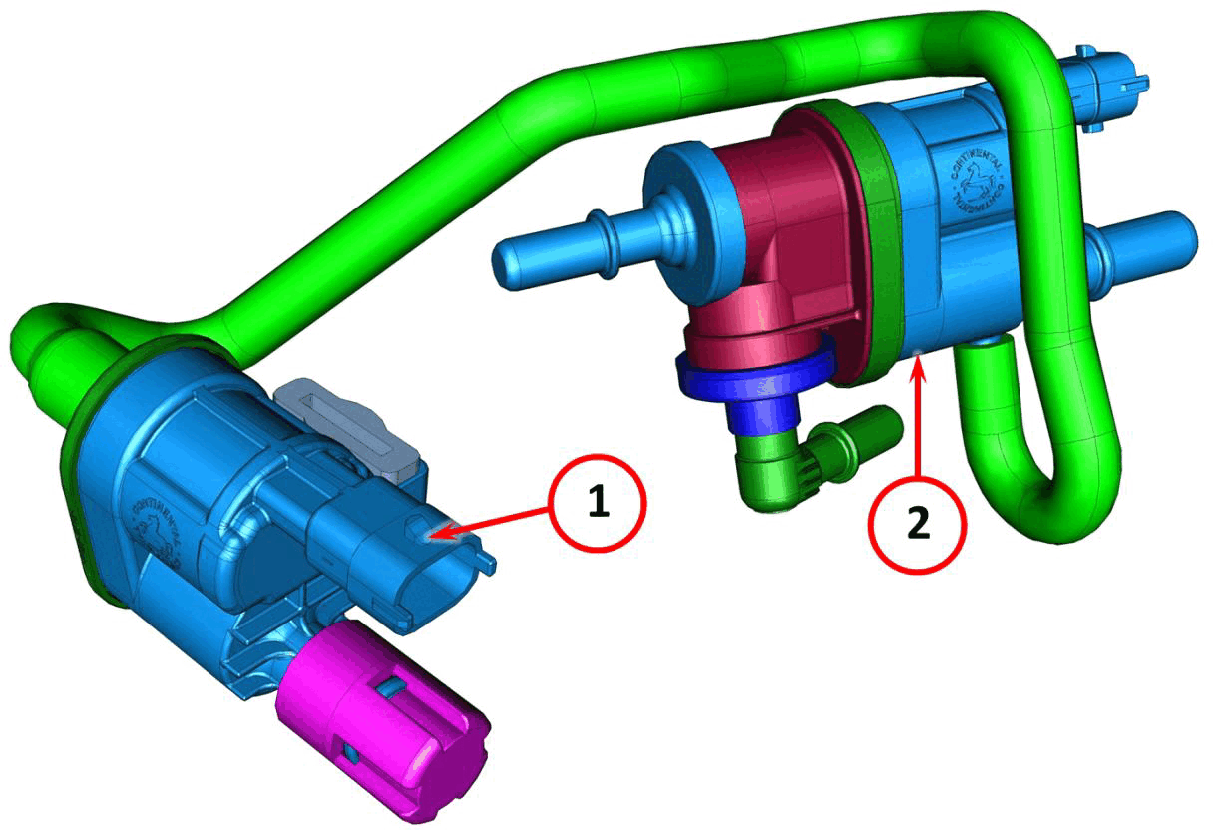
The OBD vent valve (1), controlled by the Powertrain Control Module (PCM), shares the fuel vapor inlet from the vapor canister with the evaporative emissions purge solenoid (2).
The intake manifold of a turbocharged engine sometimes operates with a positive pressure. This pressurized airflow must not be allowed to backflow into the vapor canister. The OBD vent valve (1) is used to relieve vacuum during boost.