Description And Operation
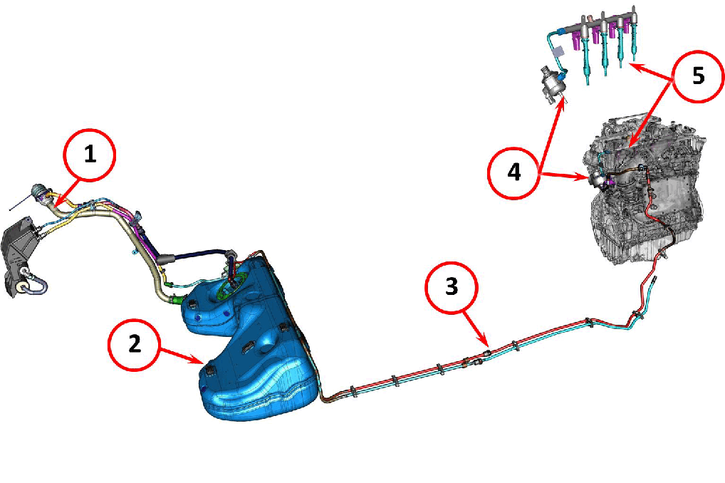
The engine is equipped with Gasoline Direct Injection (GDI) where the tip of the fuel injector is inserted into the cylinder head to allow it to inject the fuel directly into the combustion chamber.
The fuel delivery system consists of the following main components:
- Fuel filler pipe
- Fuel tank complete with fuel pump module and level sensors
- Fuel supply pipe from the fuel pump module to the high pressure fuel pump
- High pressure fuel pump
- Fuel rail
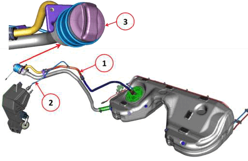
The fuel filler pipe is closed at the end with a cap (3) that has no key-closure device. The "overflow" fuel breather and vapor recovery pipe (2) is positioned a few centimeters lower from where fuel is introduced. This pipe is connected to the fuel vapor line to the active vapor canister pipe (2) that carries the fuel vapors to the inlet of the active charcoal filter box.
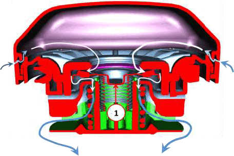
The fuel cap allows air to enter the tank but at the same time prevents fuel vapors from exiting. When the fuel level in the tank goes down, a vacuum is created in the fuel filler pipe that overcomes the spring pressure, opening the valve (1) allowing air to enter through small slits in the cap's sides.
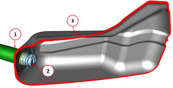
On the end of the fuel filler pipe (1) inside of the fuel tank (3) there is an Inlet Check Valve (ICV) (2) that allows the fuel to enter the fuel tank but prevents the fuel and vapors in the tank from returning up the fuel filler pipe.
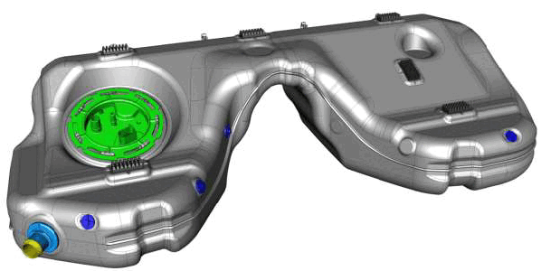
The tank has the classic "saddle" shape in order to create the space needed for the drive shaft and the exhaust pipes.
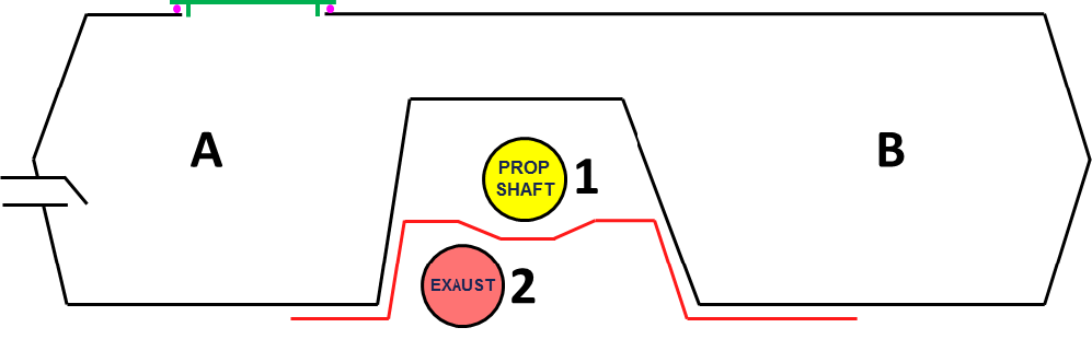
The tank is divided into two chambers, the main chamber (A) and the larger transfer chamber (B). The drive shaft (1) and exhaust pipe (2) are positioned between the two chambers.
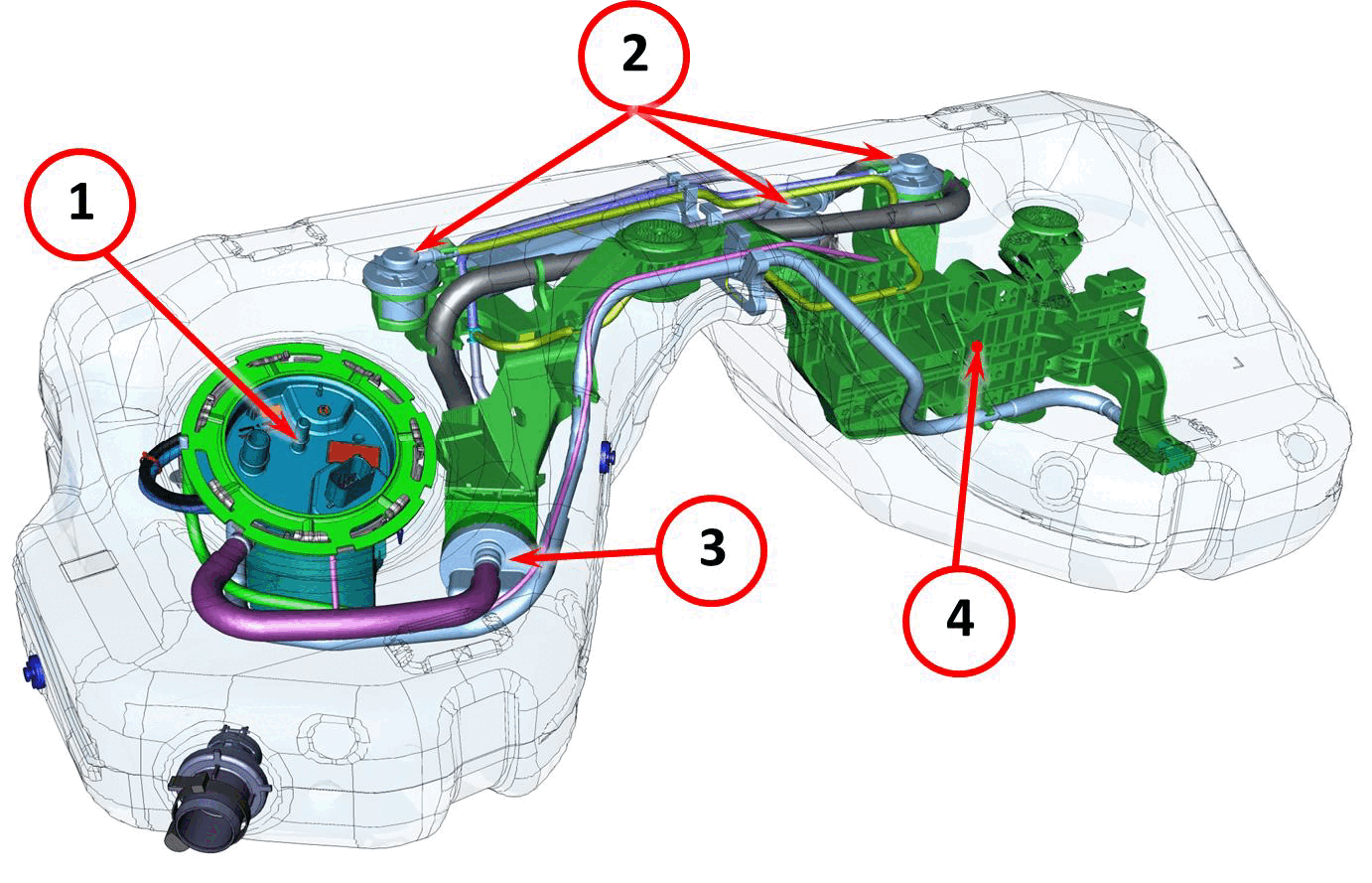
There are components inside the fuel tank to supply fuel to the high pressure system and "vent" fuel vapors towards the active charcoal canister:
- Fuel pump module
- Vent valve
- Fuel vapor accumulator
- Anti-shock support
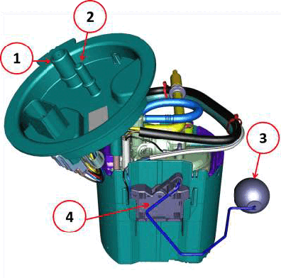
The fuel pump module is placed in the main chamber (A) and is controlled by the Fuel Pump Control Module (FPCM) which is located outside of the fuel tank. Refer to MODULE, FUEL PUMP CONTROL, DESCRIPTION AND OPERATION .
Components of the fuel pump module are:
- Pipe connection to send fuel vapors to the active charcoal canister
- Pipe connection to send fuel to the high pressure fuel pump
- Main chamber A float
- Main chamber A level sensor
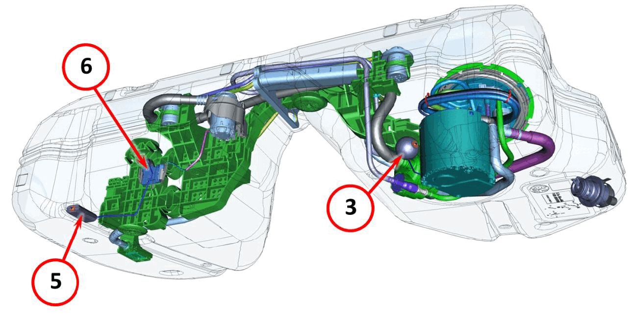
There are two level sensors inside the fuel tank. The sensor that measures the main chamber A level and one that measures the level in the transfer chamber B.
Components of fuel level sensing are:
3. Main chamber A float
5. Transfer chamber B float
6. Level sensor for transfer chamber B
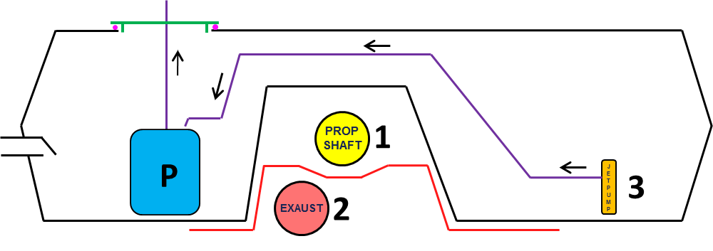
As well as the double level sensor, the fuel pump module has two fuel pick-ups. The need for two pick-ups is due to the tank shape. The fuel tank is divided into two chambers due to the location of the drive shaft (1) and exhaust pipe (2). In the main chamber, the pump (P) sucks the fuel from a basket in the lower part of the fuel pump module. In the transfer chamber, the fuel is sucked up by the immersed pipe (3).
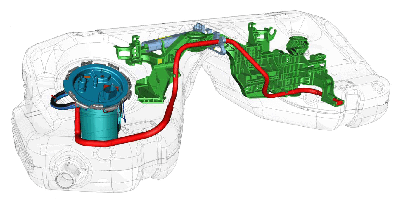
The purpose of the two immersed pipes (one of which is in the pump basket), is to ensure that the pump basket (where the pump sucks from) is always full of fuel. The two immersed inlets use the venturi effect to make fuel enter the basket.
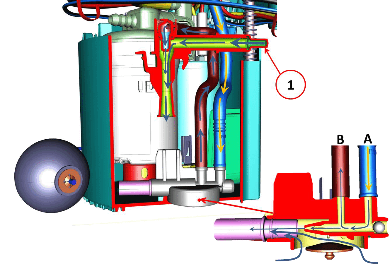
To suck fuel up through the immersed inlet in the basket, a flow of fuel (A) is sent from one of the electric pump outlets to a venturi connected to the immersed pipe. The fuel flow passing through the venturi creates the necessary vacuum to suction the fuel from the tank. The suctioned fuel contributes to maintaining the fuel level in the basket.
The fuel flow sent from the pump to the venturi, (A) in part flows back upwards (B) to supply the venturi that allows suction from the transfer chamber float connection (1).
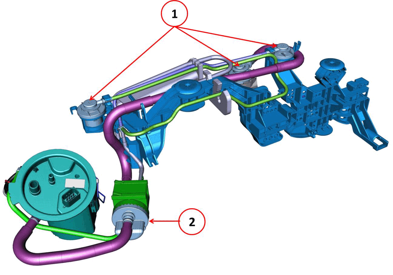
There is also a fuel vapor separation system inside the fuel tank that uses the vent valves (1) to prevent fuel flow to the vapor separator (2) and only allow the vapors to pass. The fuel vapors converge inside the separator (2) where they are sent to the active charcoal canister.
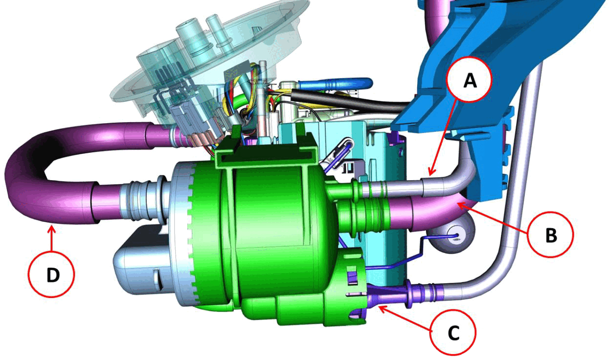
The fuel vapor separator receives vapor from the side vent valves (A) and central vent valve (B). A venturi pipe (C) sucks any remaining fuel from the separator and only fuel vapor is sent to the active charcoal filter.
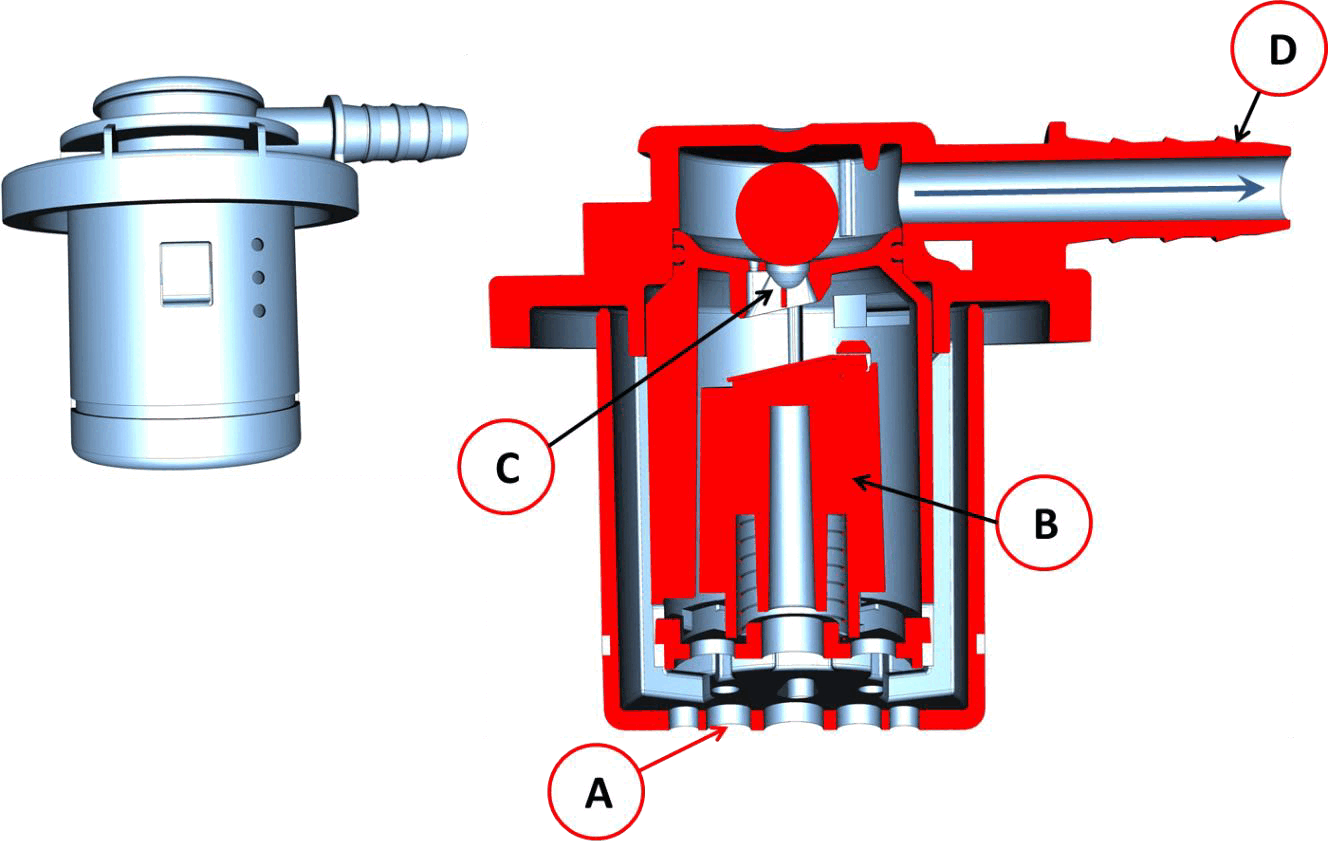
The vent valves are placed in the upper part of the fuel tank. When refueling, the fuel level rises until it enters the holes in the bottom of the valve (A). The float (B) goes up at the same time as the fuel level until it closes the passage hole (C). This way, fuel is prevented from entering fuel vapor separator. When the fuel level is below the vent valve, float (B) opens up the passage hole (C). When the vapor pressure rises inside the tank, the ball above the passage hole (C) lifts up, allowing the vapors to pass (D).
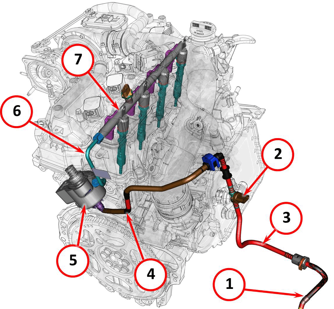
Fuel is sent from the fuel pump module piping (1) to the high pressure pump (5) through a pipe that contains the pressure and temperature sensor (2) and a metal connection pipe (4).
The high pressure system is composed of the high pressure fuel pump (5), fuel rail with fuel injectors (7) and supply pipe from the pump to the fuel rail (6).
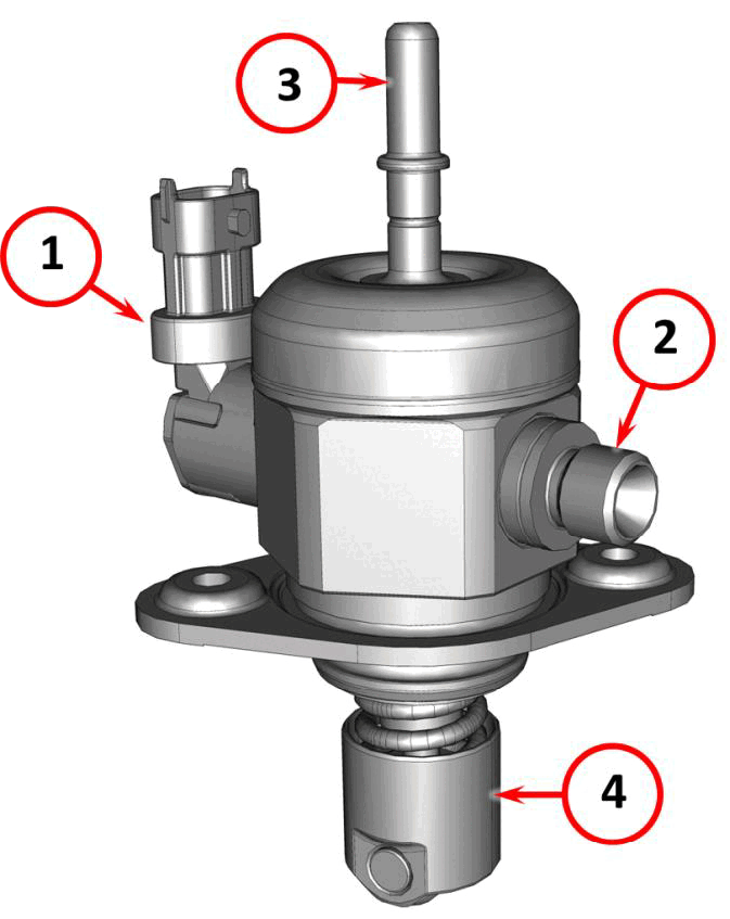
The high pressure fuel pump features:
- Flow rate regulator
- Fuel supply to fuel rail
- Fuel intake
- Roller cup
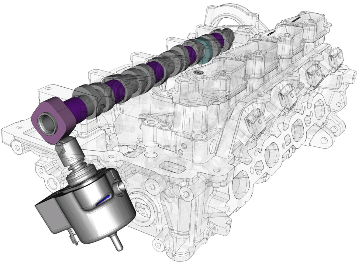
The high pressure fuel pump is directly operated by the camshaft. A roller cup is used between the cam lobe and the pump plunger stem to reduce friction.
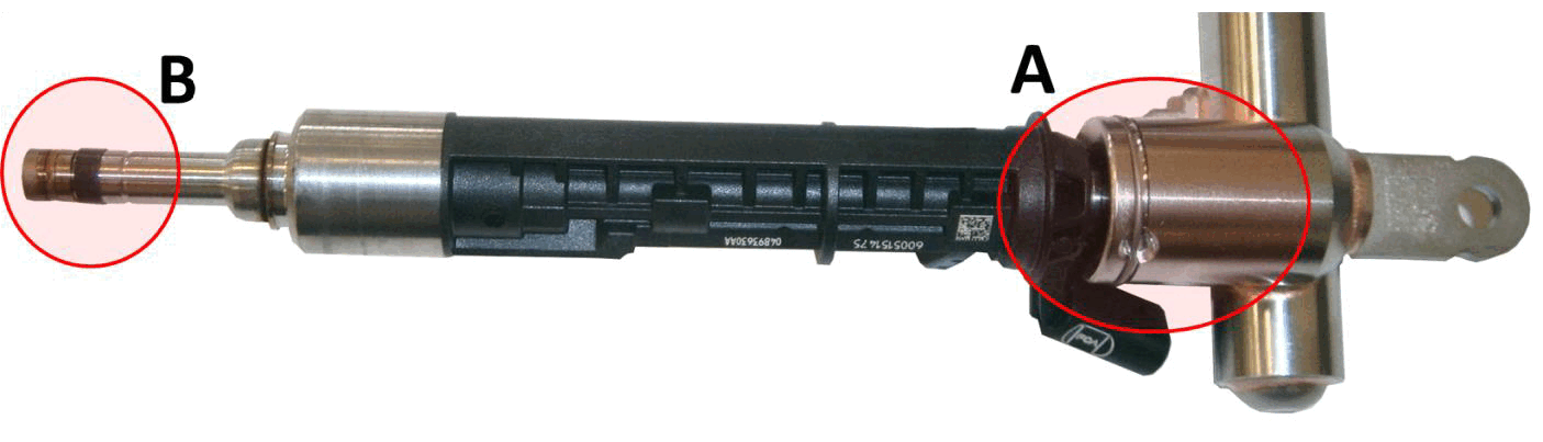
There are two areas of concern when servicing the fuel injectors, the fuel rail connection (A) and the injector tip (B).
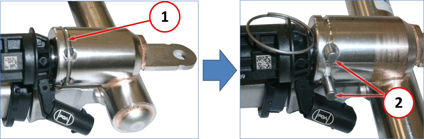
At point A, the fuel injector is held in the fuel rail by two pins (2) and a retaining ring (1).
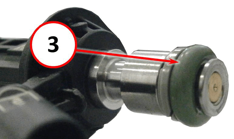
By removing the ring and the two pins, it is possible to remove the fuel injector from the fuel rail. There is an O-ring (3) on the end of the fuel injector to provide a seal to the fuel rail.
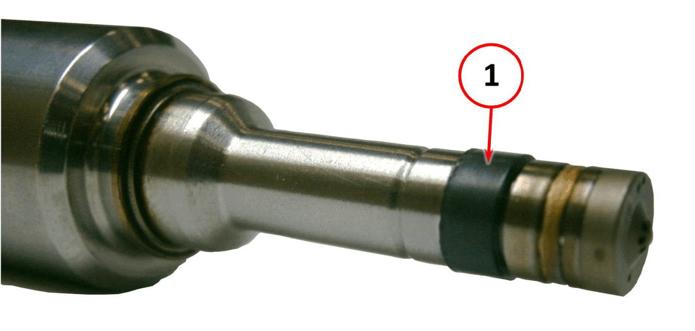
At point B, there is a Teflon ring that seals the tip of the fuel injector to the cylinder head.
The O-ring, which seals the fuel injector to the fuel rail, and the teflon ring, which seals the injector tip, must be replaced every time the fuel injector is removed from the engine. The procedure for removing and installing the fuel injectors and for replacing the Teflon ring on the injector tip requires the use dedicated tools.