Description And Operation
DESCRIPTION
The Antilock Brake System (ABS) regulates the braking pressure applied to the wheels, preventing the loss of grip. The system is designed to be incorporated with the braking system (using the same hydraulic fluid) without interrupting the operation of the braking system itself if the ABS fails. Four wheel speed sensors, located on each of the four wheels, indicate the speed of each wheel to the ABS module, recording any situations involving locking, slipping or loss of grip. In these situations, the ABS module controls the solenoid valves which regulates pressure in the hydraulic circuit, preventing the wheels from locking. This ensures optimum handling of the vehicle and excellent stopping distances.
The sensors are active, supplied by the control unit; they consist of a magnetic resistive receiver with a magnetic codifier incorporated in the hub bearing so that the signal is less affected by electromagnetic interference and variations in temperature. The Integrated Control Unit (ICU) also controls the distribution of the braking load between the front and rear axles, meaning that the mechanical load proportioning valve used previously can be dispensed with Electronic Brake Distribution (EBD). The ICU is equipped with a self-diagnosis function; when an error in the ABS function is detected, the warning light is illuminated and the system is deactivated at the same time. In these conditions the vehicle brakes use the traditional system only. When the ICU detects an error which also affects the EBD function, the ABS, low brake fluid, and parking brake warning lights will be illuminated on the Instrument Panel Cluster (IPC).
In these conditions the rear braking distribution control is deactivated; the driver must therefore proceed very carefully to the first authorized service center. The ICU calculates the speed of the vehicle starting from the figures that are supplied by the wheel speed sensors (with the ICU calculating the average value) and from the circumference of the wheels themselves, supplied by the Body Control Module (BCM); this speedometer signal is then sent, via the CAN, to the nodes that require this information. Various active safety systems are combined into the "traditional" ABS:
- Drag Torque Control
- Electronic Stability Control (ESC)
- Traction Control (TC)
- Panic Brake Assist
- Hill Start Assist (HSA)
- Dynamic Steering Torque
These systems interface with the engine control and traction control system. The ICU supply lines are protected by two dedicated fuses in the Power Distribution Center (PDC), via the CAN line, the brake control unit connects to the instrument panel to manage the "ABS failure" warning light, and if there are problems with the EBD function, the "insufficient brake fluid level and handbrake engaged" warning light as well as the "ESP" warning light. The "brake pad wear" warning lights are managed by the Body Control Module (BCM) and not the ABS module.
The ICU does not envision the use of any type of power brake as braking assistance since there is an electric-mechanical actuator that creates the correct pressure conditions for braking. The brake pedal, in normal functionality conditions, does not directly generate the hydraulic braking pressure that actuates the calipers. Since the brake pedal is free of the function of creating brake pressure, the system is able to supply different responses (feedback) of the brake pedal according to the position assumed by the mode selector of the DSU guide.
During the intervention of one of the braking systems, such as the ABS, the typical and characteristic "pulsations" are not perceived.
The ICU reaches the brake pressure in the shortest time, with the highest pressure, with encumbrance volumes and weights lowest of all the braking systems currently in use. These advantages result in a considerable reduction in braking distance.
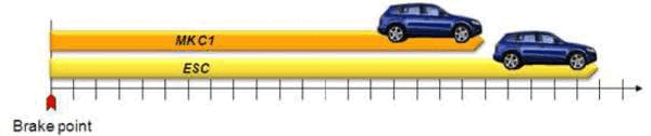
Given that the correct braking pressure is realized by a mechanical actuator controlled by an electrical motor, managed in turn by a specific electronic module, we can affirm that the braking system of the vehicle, of the electro-hydraulic type, is the "Brake by Wire" type.
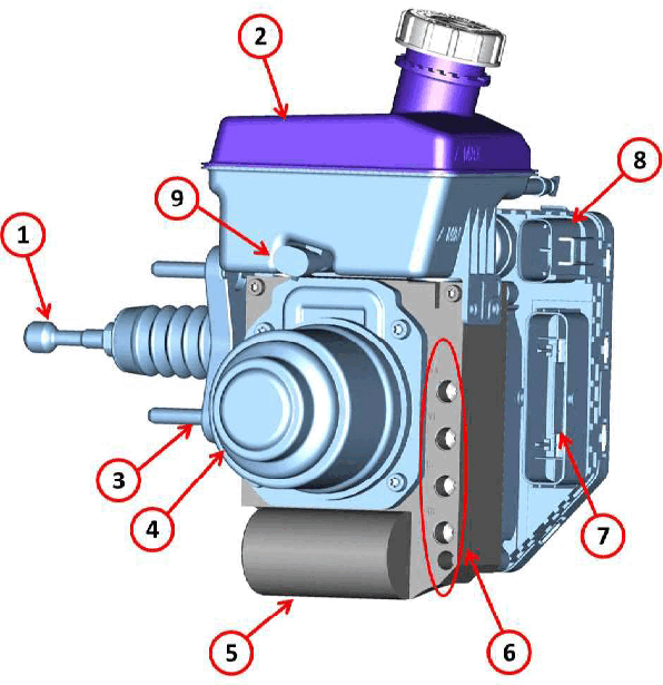
ICU components are:
- Control rod (to the brake pedal)
- Brake fluid reservoir
- Module fastening studs to bulkhead
- Brushless electrical motor
- Pedal pressure sensor
- Brake line ports for brake calipers
- ABS module connector
- Power supply Connector
- Tank oil level sensor
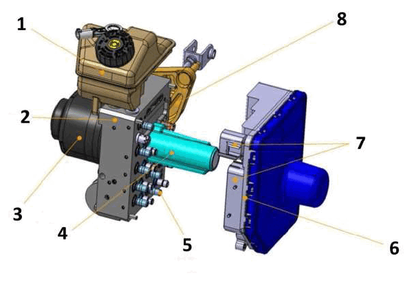
- Brake fluid reservoir
- Hydraulic body
- Electric motor
- Linear actuator with ball screw
- Valves
- ABS module
- Electrical connectors
- Mounting point
Master Cylinder
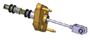
The brake pedal is directly connected to the master cylinder. The master cylinder is designed to reach pressures higher than the traditional applications with power brakes because, in the event of system failure, the driver must be able to stop the vehicle acting on the brake pedal without exerting excessive force.
The master cylinder consist of a cylinder, two pistons, an O-ring seal and a sensor actuated by the position of the pedal stroke.
The sensor is a contact-less type. The position of a magnetic ring, joined to the primary piston, is read by an electromagnetic transducer.
Pedal Pressure Simulator
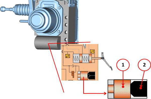
It has the function of warning the driver of a specific response of the brake pedal (Feedback). The simulator is fundamental to the operation of the system as it provides the correct progression to the brake pedal avoiding the feeling by the driver of a pedal with a "long" stroke. The simulator consists of a plunger (1), a spring and a rubber element (2). A solenoid valve and a unidirectional mechanical valve complete the simulation system of the brake pedal pressure. The electrical valve connects the discharge of oil from the master cylinder with the simulator; the mechanical valve manages the outflow of the oil from the simulator when the brake pedal is released.
Electric Motor

The electric motor which produces the brake pressure is of the brushless type and the stator coils are connected to a three-phase inverter inserted into the electronic body of the ABS module. The electric motor has a revolution sensor to acquire the mechanical angle of the rotor. Based on this information, the engine control module calculates the angle of the phase with which to drive the electric motor inverter.
Ball Screw
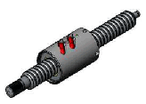
The ball screw is the element that physically creates brake pressure. It is inserted inside a cylinder; it translates the rotational movement of the rotor into linear movement of the actuator piston.
The software estimates the volume of oil that serves for the proper operation of the braking system. If a loss in the hydraulic circuit of the braking system is detected, the ABS module can activate one of the valves of hydraulic circuit exclusion, to exclude the part where there is the loss of oil. By means of the discharge valves, the ABS module manages the antilock of the wheels. When one of these is active, the pressure on the hydraulic circuit decreases because the oil is sent to the tank and by doing so prevents wheel locking.
ABS Module Operating Logic
The ICU braking system continuously performs tests to know the status of operation of the entire braking system.
The ICU monitors the pressures by means of the specific sensors and processes the amount of oil volume absorbed by the braking system to determine possible losses in the hydraulic circuits and evaluates the correct operation of the master cylinder and the actuator.
If a loss is found in a hydraulic circuit, the system is able to isolate it and bypass it, keeping the other hydraulic circuit in operation.
The hydraulic circuits of the braking system are two, isolated and independent from each other; they correspond to:
- The primary hydraulic circuit: it supplies the left front caliper and the right rear caliper.
- The secondary hydraulic circuit: it supplies the right front caliper and the left rear caliper.
The braking system can operate according to two distinct modes:
- Normal operating function called "Brake by wire"
- Recovery operation called "Fallback"
System Operation
Following are the symbols, with related explanations to help in understanding the functioning of the system:
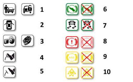
- Vehicle unlocking
- Door opening
- Ignition and Start
- Brake pedal applied
- Brake pedal released
- Electric brake available/Electric brake not available
- Control of dynamic functions, available/Control of dynamic functions, not available
- Brake failure warning light on/Brake failure warning light off
- ABS failure warning light on/ABS failure warning light off
- ESC failure warning light on/ESC failure warning light off.
Normal Wakeup Situation of the System
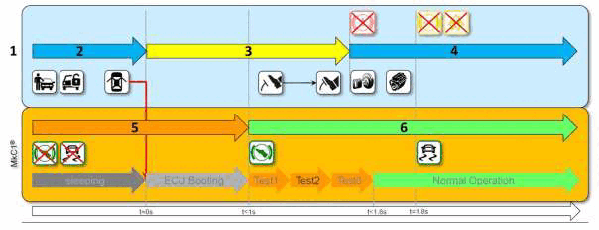
- Driver and vehicle
- Entry into vehicle
- Position in vehicle
- Switch on - startup - shut off
- Brake by wire mode not available
- Brake by wire mode available
From the opening of the vehicle door the ABS module is awakened. In less than 1.8 seconds it starts and performs the self-diagnosis test (primary circuit, master cylinder and the secondary circuit). The driver enters and sits in the driver's seat pressing the brake (in case of an automatic transmission) and starts the engine. The figure above shows that in less than 1.8 seconds, the brake control module is ready for normal "Brake by wire" operation.
Normal Sleeping Situation of the System
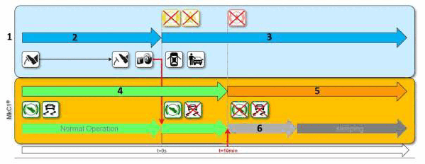
- Driver and vehicle
- Brake pressed - vehicle shut OFF
- Leaving the vehicle
- Brake by wire mode available
- Brake by wire mode not available
- ABS module shut OFF
The driver releases the brake pedal, closes the door, locks the doors and leaves. After the doors are locked, the ABS module remains active for about 10 minutes and then shuts OFF. During the 10 transitory minutes, the ABS brake control module keeps its normal operating functions active. Afterwards, it passes to "Fallback" recovery operation.
Possible System Wakeup Scenario
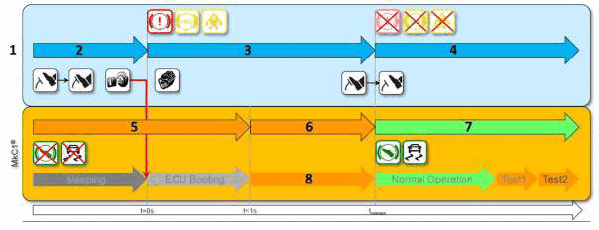
- Driver and vehicle
- Driver in the vehicle
- Switch on - start-up engine
- Move or at least release brake pedal
- Brake by wire mode not available
- Brake by wire mode available but not completely functioning
- Brake by wire mode available
- Awaiting release of brake pedal
Instead of existing the vehicle and locking the doors, the driver remains in the vehicle with the engine OFF and key OFF for a period of time sufficient for the ABS brake control module to turn OFF (sleep). Then he presses and holds brake pedal and starts engine:
- The indicator lights on the instrument panel remain lit until the driver releases the brake pedal.
- As long as the ABS module does not wake up and does not start, it does not provide the brake in by wire mode.
- Once started, the ABS module awaits the release of the brake pedal and while it is still pressed, it does not provide the "Brake by wire" functionalities and as a result, maintains the "fallback" recovery configuration.
- After the driver releases the brake pedal, the ABS module provides all the normal "Brake by Wire" operative functionalities and as soon as possible performs the routine self-diagnostic tests.
Possible Scenario One of System Shut-off .
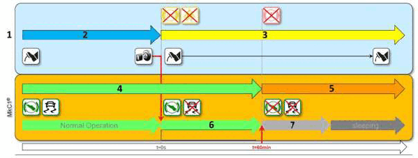
- Driver and vehicle
- Brake pedal pressed - vehicle stopped - vehicle shut OFF
- Brake pedal pressed
- Brake by wire mode available
- Brake by wire mode not available
- Brake by wire mode available but no control of function of active stability
- ABS module shut OFF
The driver presses the brake pedal, turns OFF the engine and keeps the brake pedal pressed. The ABS module keeps the braking system in the normal "Brake by Wire" operating function for up to about 60 minutes and compensates for the loss of oil volume by activating, when required, the electric motor.
Once the 60 minutes have elapsed, the ABS module switches OFF and as a result the braking system changes to the "fallback" recovery configuration.
Possible Scenario Two of System Shut-off.
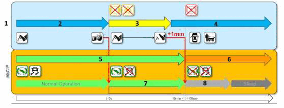
- Driver and vehicle
- Brake pedal pressed - vehicle stopped - vehicle shut OFF
- Brake pedal pressed
- Leave the vehicle
- Brake by wire mode available
- Brake by wire mode not available
- Brake by wire mode available but no control of function of active stability
- ABS module shut OFF
The driver presses the brake pedal, turns OFF the engine and keeps the brake pedal pressed for a period of between 10 and 60 minutes. As long as the pedal is pressed, the ABS compensates for the loss of oil volume activating, when required, the electric motor.
The ABS module provides all the normal "Brake by Wire" operating functionality for up to 1 minute after the brake pedal was released; afterwards the system is configured to function according to the "fallback" recovery mode.
OPERATION
Power to the pump inside the Integrated Control Unit (ICU) is supplied from the battery by a fuse protected circuit in the front Power Distribution Center (PDC).
Power to the ABS module is supplied from the battery by a fuse protected circuit in the front Power Distribution Center (PDC).
The ABS module is on the Controller Area Network - Chassis (CAN-CH) data bus and communicates directly with the BCM. The BCM is responsible for sending the signal to the IPC to illuminate the warning indicator lamp in order to alert the vehicle operator of a potential ABS concern.