Removal And Installation: Installation
In case of replacement of the pressure sensor, connect the scan tool to the vehicle, select "Radio Frequency Hub (RFH)" in the " Miscellaneous functions " and launch the procedure " Learning ID TPM sensors " carefully following the instructions.
To verify the correct operation of the sensor make sure the meter TPM is updated to the latest release. The tool automatically updates by connecting to PC with the TPM Manager software.
When the valve is removed from the rim, it is necessary to replace it with a NEW one in good condition because the rubber seal may not fit perfectly in the valve opening later on.
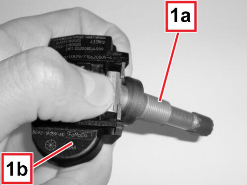
- Verify that the sensor (1b) is intact and that the hole in the wheel is in good condition
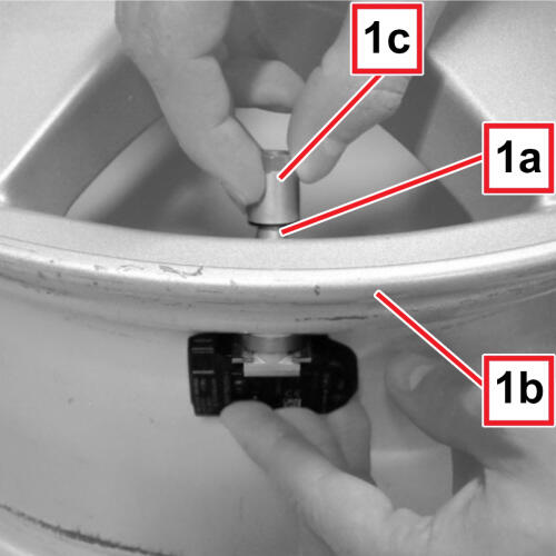
- Check that the valve stem (1a) is fully inserted into the sensor housing (1b).
- Insert the valve stem (1a) into the hole of wheel (1b) and hand-tighten the senor mounting nut (1c).
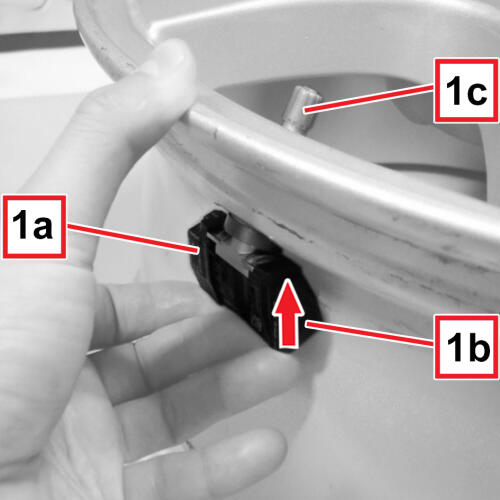
- Press the sensor (1a) from below with a vertical force (1b) so that the sensor is inserted completely within the valve stem (1c).
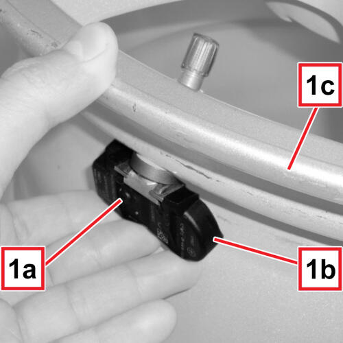
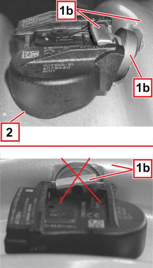
- Hold the sensor (1a) making sure to have contact (1b) with the wheel rim (1c) at least one point (left or right).NOTE:
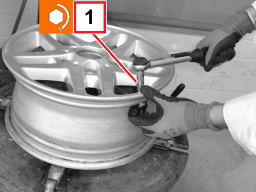
Excessive torque can damage the sensor, and insufficient torque can cause leakage.
- Tighten the TPM sensor mounting nut to the proper specification. Refer to TECHNICAL SPECIFICATIONS .
- Check that the valve is inserted completely in place and aligned with the rim flange (1b).
- Verify that the sensor is in contact with the wheel rim at least one point (left or right)NOTE:
The initial sensor position must be at 6 o'clock in relation to the hydraulic arm.
NOTE:The distance between the blade of the hydraulic arm and the sensor must always be greater than 80 mm.
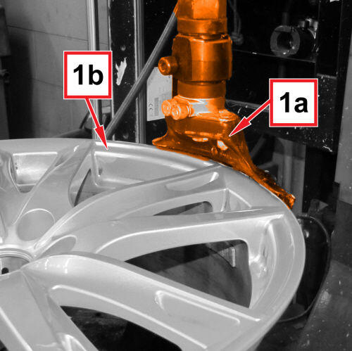
- Position the rim on the tool chuck and ensure the hydraulic arm (1a) is in contact with the edge of the rim (1b) as shown in illustrations.
- Lubricate the entire rim surface and the inner and outer tire bead area.
- Position the inner edge of the tire on the rim using the hydraulic arm.
- Turn the chuck and press on the tire by hand until it is fully fitted.
- Do the same to fit the outer edge.
- Inflate the tire to the recommended pressure.
- Tighten the valve core on the valve and remove the wheel from the tool.
- Install the tire and wheel assembly. Refer to REMOVAL AND INSTALLATION .