Forward Collision Warning System
FORWARD COLLISION WARNING (FCW) and FCW+
The purpose of the Forward Collision Warning (FCW) system is used to warn the driver of a potential front collision. The FCW system audibly and visibly prompts the driver to intervene in addition to jerking the brake (tactile warning). Finally, the system will activate the braking system in an attempt to help the driver avoid the collision. In all cases, the driver is always responsible for avoiding a collision by controlling the vehicle by braking and steering. The system assists driving only.
The FCW+ system involves various modules for operation and is mainly based on information from the Adaptive Cruise Control (ACC) module, which in addition to containing the radar module, manages the operation strategies of the entire system to detect obstacles on the vehicle path and determine their position (longitudinal, side distance) and speed.
The ACC module receives further information from the Forward Facing Camera Module (FFCM) (the camera located behind the windshield) to determine potential collisions with objects on the vehicle path.
The FCW+ can recognize impact situations against moving objects (in the same direction of travel as the vehicle), static objects (vehicles stopped on the lane) and low speed smaller objects, such a pedestrians (crossing the lane).
The ACC module and the FFCM communicate with each other by means of a private and dedicated Controller Area Network (CAN) - C bus data system.
The FCW+ system operates at high speeds to approximately 200 km/h (125 mph).
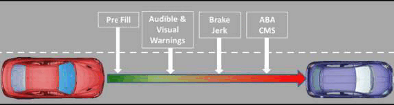
The FCW+ function combines various sub-functions, such as:
- Pre-fill: preparation of the braking system for emergency braking by slightly increasing pressure in the brake circuit.
- Audible and Visual Warnings: : to attract the driver's attention.
- Brake Jerk: as a second and stronger warning of the approach of a potential dangerous situation (function active for approaches against other vehicles only)
- ABA: if the driver applies the brakes to avoid the potential impact, the system activates the functions managed by the Automatic Braking System (ABS) module.
- CMS: if the driver does not react to the potential impact warnings, the system will be activated automatically to stop the vehicle and prevent/mitigate the impact.
The FCW+ system is active if:
- The speed is higher than approximately 7 km/h (4 mph) and lower than approximately 200 km/h (125 mph) if the obstacle is moving.
- The vehicle speed is between 7 km/h (4 mph) and 50 km/h (if the obstacle is stationary). Above 50 km/h (31 mph), only warning messages and the buzzer are available.
- It is correctly programmed on the vehicle menu.
- The front seat belts are fastened and the driving mode selector is not in the "RACE" position.
Based on vehicle speed and the status of the obstacle in front of it (stationary or moving), FCW+ makes it possible to avoid or mitigate a possible collision. If the vehicle is about to collide with the obstacle, FCW+ decelerates the vehicle. The deceleration of the vehicle may be enough to avoid the impact, or may mitigate the impact itself.
The FCW+ function will operate the brakes (decelerating the vehicle) only if the driver ignores all warnings and indications that the system has sent in the previous instants. Brake intervention is the "last stage". The braking will occur only after the last instant in which the driver can avoid the impact has elapsed. The system is designed to allow the driver the possibility to manage the hazardous situation autonomously up to the last useful moment.
The FCW+ system cannot be tested by the scan tool. It is not possible to check the operation of the FCW+ system during a test drive by simulating circumstance that would cause a FCW+ event to occur. To check the correct operation of the FCW+ function, the diagnostic scan tool should be used to check for Diagnostic Trouble Codes (DTC) in the ACC module and the FFCM. The scan tool should also be used to verify that the system calibration is correct.
The FCW+ system is normally active. The driver can deactivate the system by using the vehicle configuration menu. With the FCW+ system off, the system will be automatically reactivated when the ignition status changes to KEY ON.
The driver can select the sensitivity of the FCW+ warnings (near, medium and far) using the vehicle menu. Near means a less sensitive warning and far a more sensitive warning.
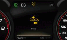
Example of the FCW+ visual warning shown in the 7 inch display of the Instrument Panel Cluster (IPC).
When the vehicle is equipped with a manual transmission and the clutch pedal is not pressed can cause the engine to stall because of the vehicles braking system being applied for a few seconds.
COMPONENT LOCATION
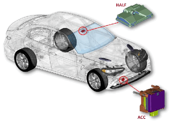
The Forward Collision Warning Plus (FCW+) function is managed by the ACC module (radar located behind the front bumper) and by the FFCM - HALF module (located behind the windshield near the rearview mirror).
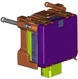
The ACC module includes the software needed for operating the ACC+ and the FCW+ systems. The ACC module determines the distance to a target vehicle and the speed at which the target vehicle is approached. If the ACC module determines the need to intervene, it sends a message to the other modules over the CAN-C data network to activate the audible, visual and tactile warnings while requesting activation of the torque reduction via the Powertrain Control Module (PCM) and to the Body Control Module (BCM) to illuminate the brake lights.
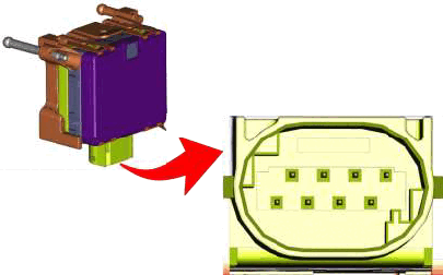
The ACC module pin-out
| PIN | DESCRIPTION |
|---|---|
| 1 | Ground |
| 2 | CAN 1 H |
| 3 | CAN 1 L |
| 4 | N/A |
| 5 | Private CAN |
| 6 | Private CAN |
| 7 | N/A |
| 8 | 12v Power |
Whenever the ACC module must be replaced with a new one, it must be calibrated by diagnostic scan tool
Refer to MODULE, ADAPTIVE CRUISE CONTROL (ACC), MODULE PROGRAMMING .
OPERATION OVERVIEW
- The ACC module is power circuit is protected by a fuse located within the BCM.
- The ACC module and FFCM are connected via a dedicated Private CAN bus.
- The FFCM receives an ignition operated power feed from the BCM.
- The BCM receives direct battery fuse protected power via the prefuse assembly on the battery.
- The PCM is connected, via the CAN network, to the BCM and the IPC to manage the visual messages located on the IPC.
- The control switch for deactivating the FCW+ system is located on the steering column stalk. This switch sends the off signal to the BCM.