Sentry Key Immobilizer System: Operation
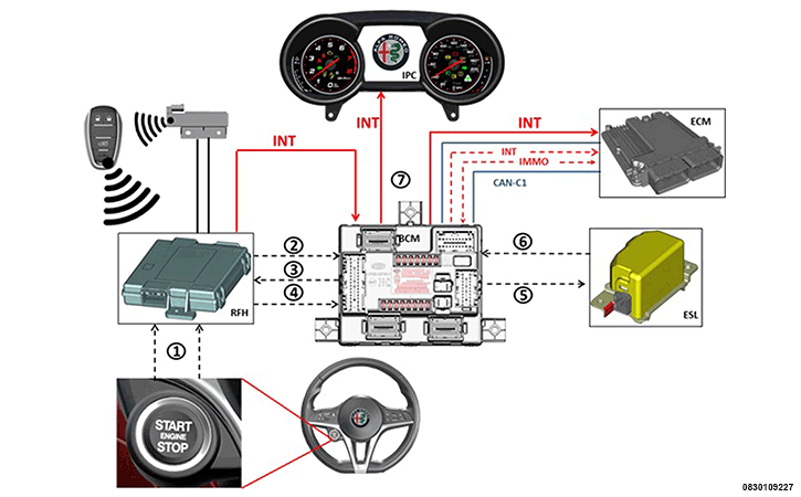
The "keys" (Finger Operated Button with Integrated Key (FOBIK)) are stored in the Radio Frequency Hub (RFH). When the vehicle user presses the Start/Engine/Stop button (1), it sends the information that the button has been pressed to the RFH (via two analogue signals, one of which is a "redundant run"). At this point the RFH informs the BCM that the button has been pressed (2). The BCM, in turn, sends a request (3) to the RFH to identify the FOBIK key. If the RFH recognizes the FOBIK (inside the car) as a "valid FOBIK", it sends this information to the BCM (4), which will send a request to the ESL module to unlock the steering column (5). When unlocked, the ESL provides confirmation to the BCM (6), which communicates the status of "steering unlocked" to the RFH. At this point, the latter distributes the key-ON power supplies +15 (the panel turns on). The "key-ON" state is sent at the same time via CAN to the PCM engine control module.
With ignition ON (+15), the encrypted dialogue (minicrypt) is triggered between BCM and PCM. The PCM sends a secret code request (IMMO CODE REQUEST) to the +15 for the BCM, which will respond to the request (IMMO CODE RESPONSE). If the outcome of the dialogue is positive, the PCM will permit the engine to be started. If the outcome is negative, the PCM will not enable engine starting. In this case, the BCM will send a request to the Instrument Panel Cluster (IPC) to switch on the Code Immobilizer warning light.
NOTE: With the start enabled, to start the engine (command to the starter motor), press the clutch pedal and then press the Start/Engine/Stop button again. In the case of an automatic transmission, press the brake pedal.
The hardwired circuits between components related to the immobilizer system may be diagnosed using conventional diagnostic tools and procedures. Refer to the appropriate wiring information. The wiring information includes wiring diagrams, proper wire and connector repair procedures, details of wire harness routing and retention, connector pin out information and location views for the various wire harness connectors, splices and grounds.
However, conventional diagnostic methods will not prove conclusive in the diagnosis of the immobilizer system or the electronic controls and communication between other modules and devices that provide some features of the immobilizer system. The most reliable, efficient and accurate means to diagnose the immobilizer system or the electronic controls and communication related to immobilizer system operation requires the use of a diagnostic scan tool. Refer to the appropriate diagnostic information.