Test G: Trunk Release Is Inoperative (Except Police Model)
NOTE:
Police models are equipped with 2 trunk release switches, located at center of dash panel. See TEST H: TRUNK RELEASE IS INOPERATIVE (POLICE MODEL) .
NOTE:
Perform all voltage and resistance tests using an Digital Volt-Ohm Meter (DVOM) with a minimum 10-megohm input impedance, unless stated otherwise in test procedure. Use ohmmeter to isolate wiring harness shorts or opens.
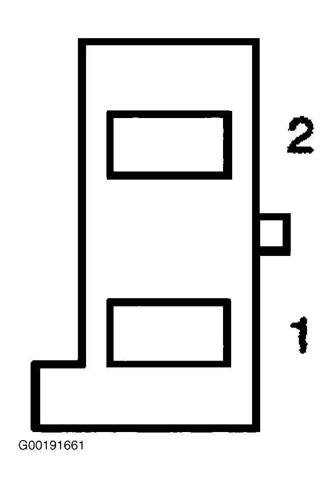
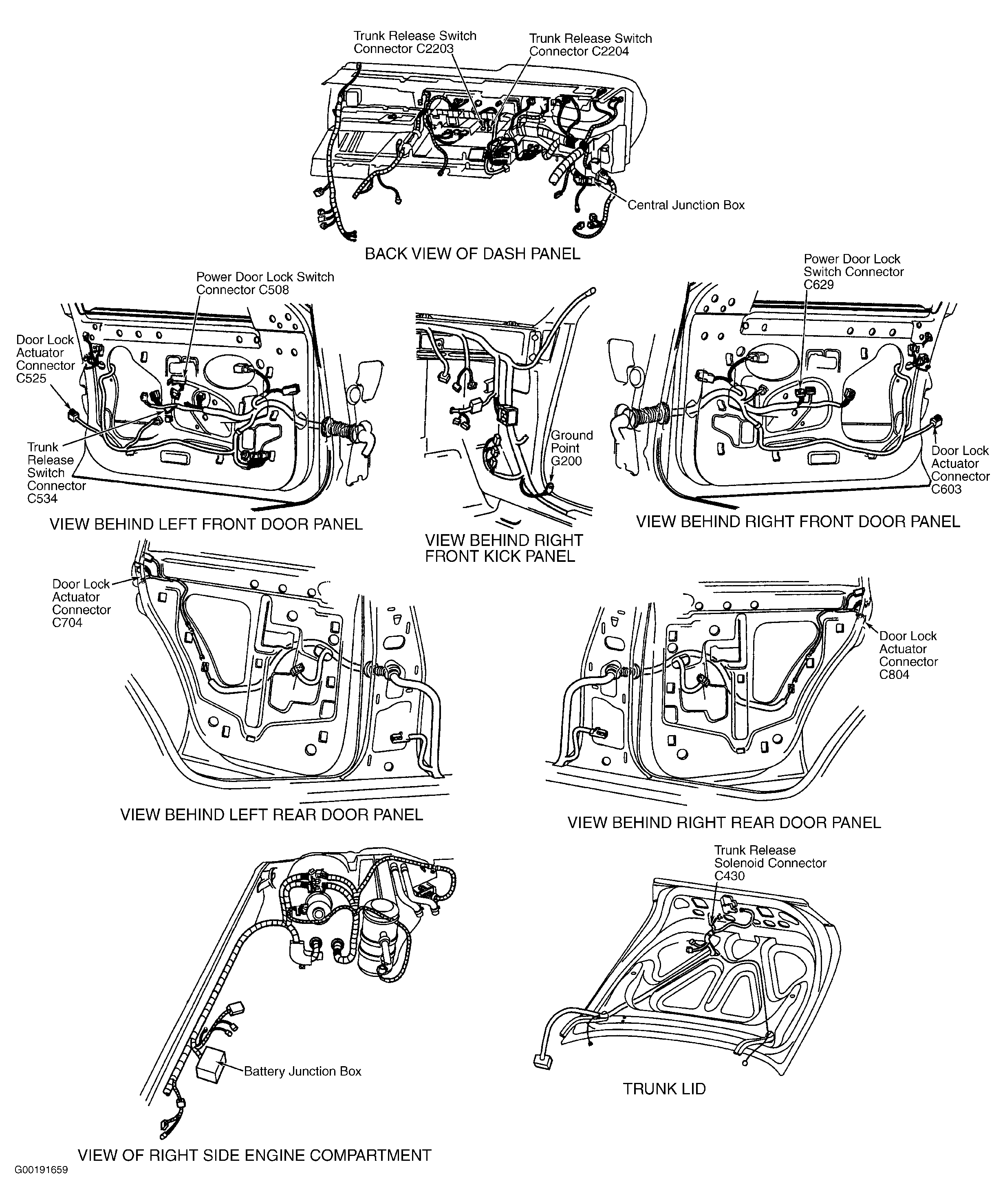
- Turn ignition switch to LOCK position. Remove door trim panel. See DOOR TRIM PANEL under REMOVAL & INSTALLATION. Disconnect trunk release switch 2-pin harness connector C534, located behind door trim panel. See Figure. Measure voltage between ground and trunk release switch harness connector C534 terminal No. 1 (Black/White wire). See Fig 1. See WIRING DIAGRAMS . If voltage is greater than 10 volts, go to next step. If voltage is 10 volts or less, repair open circuit in Black/White wire between trunk release switch and Battery Junction Box (BJB) located at right front of engine compartment. After repair, test system for normal operation.
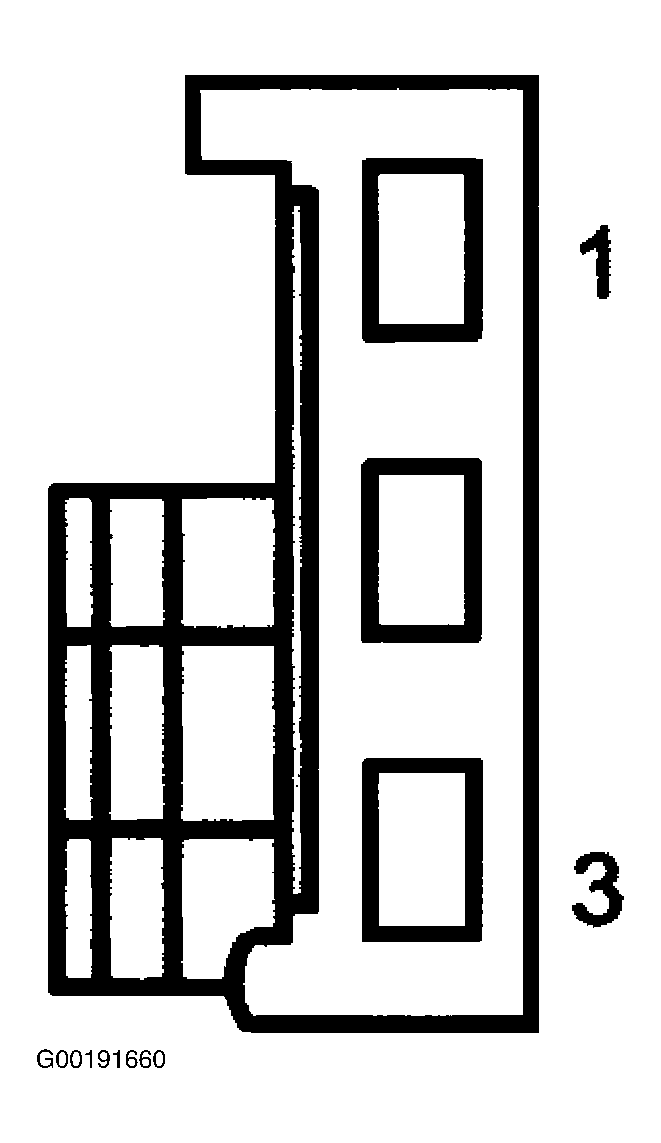
- Reconnect trunk release switch. Disconnect trunk release solenoid 3-pin harness connector C430, located at center of trunk lid. See Figure. While pressing trunk release switch, measure voltage between ground and trunk release solenoid harness connector C430 terminal No. 2 (Violet/Yellow wire). See Fig 2. See WIRING DIAGRAMS . If voltage is 10 volts or less, go to next step. If voltage is greater than 10 volts, go to step 4.
- Disconnect trunk release switch harness connector C534. Measure resistance between trunk release switch harness connector C534 terminals No. 2 and trunk release solenoid harness connector C430 terminal No. 2 (Violet/Yellow wire). See Fig 1 and Fig 2 . See WIRING DIAGRAMS . If resistance is 5 ohms or less, replace trunk release switch. See TRUNK RELEASE SWITCH under REMOVAL & INSTALLATION. If resistance is greater than 5 ohms, repair open circuit in Violet/Yellow wire between trunk release switch and trunk release solenoid. After repair, test system for normal operation.
- Measure resistance between ground and trunk release solenoid harness connector C430 terminal No. 3 (Black wire). See Fig 2. See WIRING DIAGRAMS . If resistance is 5 ohms or less, replace trunk release solenoid. If resistance is greater than 5 ohms, repair open circuit in Black wire between trunk release solenoid and ground point G200 located behind right kick panel. See Figure. After repair, test system for normal operation.