Differential Case: Removal
- Remove the axle shafts (4234). For additional information, refer to AXLE SHAFT .
- Wipe the lubricant from the internal working parts and inspect the parts for wear and damage.
- Rotate the differential assembly to check for roughness indicating bearing/gear damage.
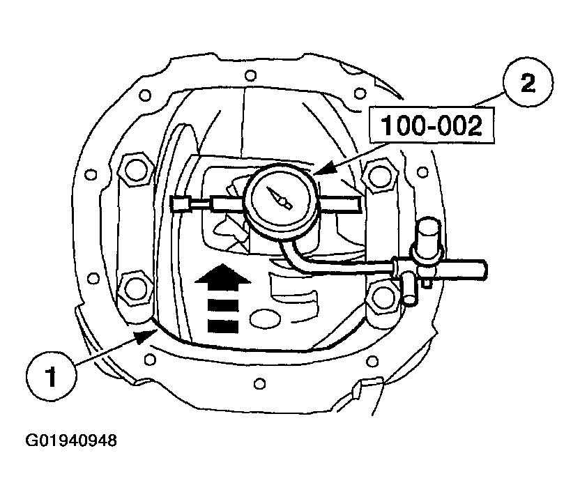
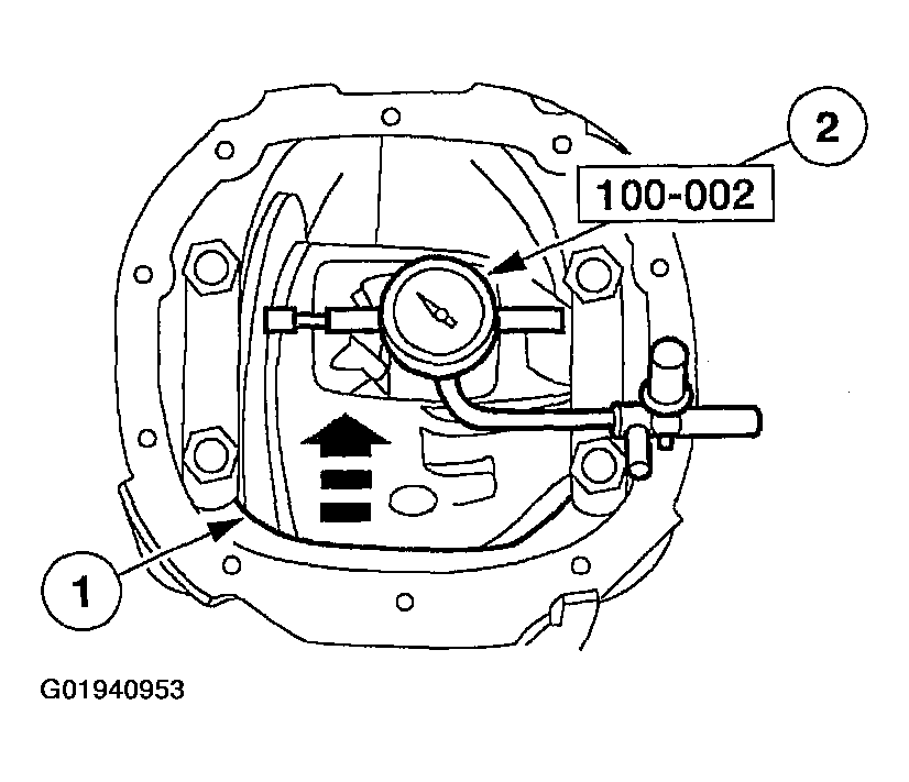
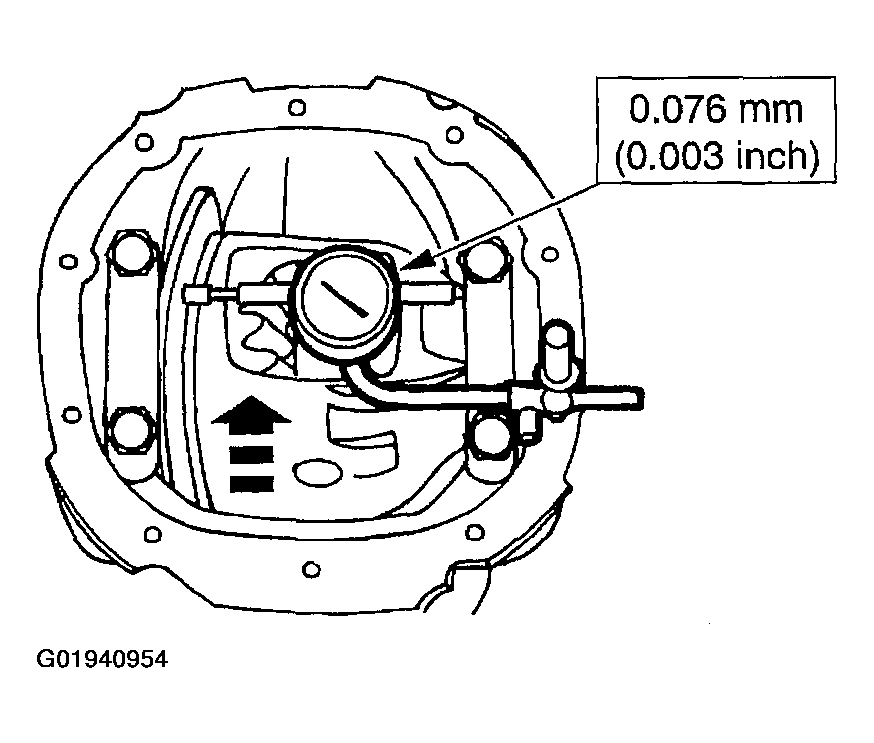
- Using the special tool, measure and note the differential ring gear backface runout.
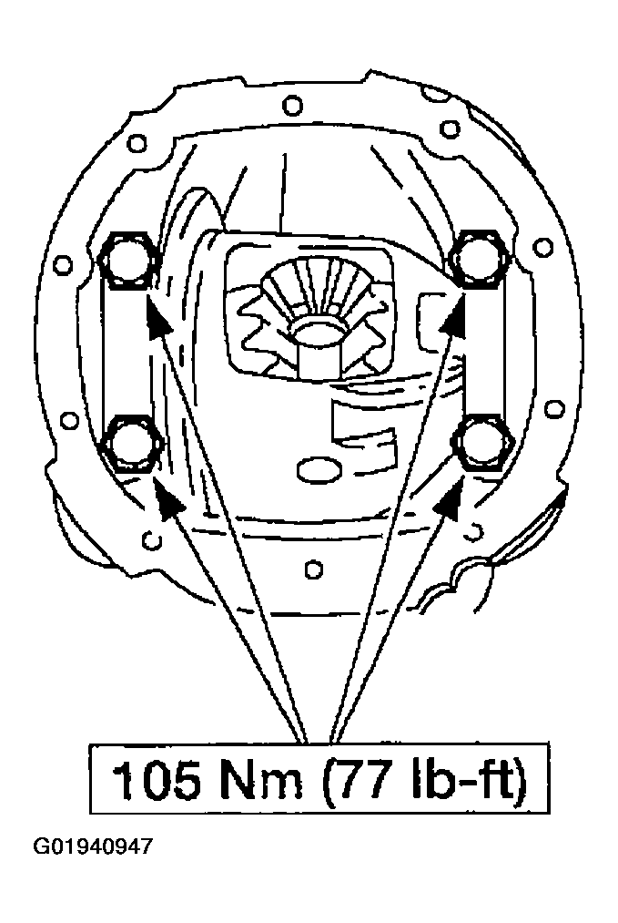
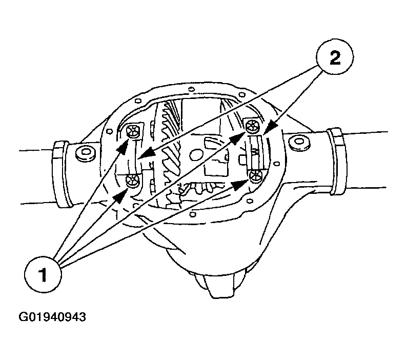
- Remove the differential bearing caps.
- Remove the bolts.
- Remove the differential bearing caps.
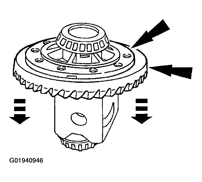
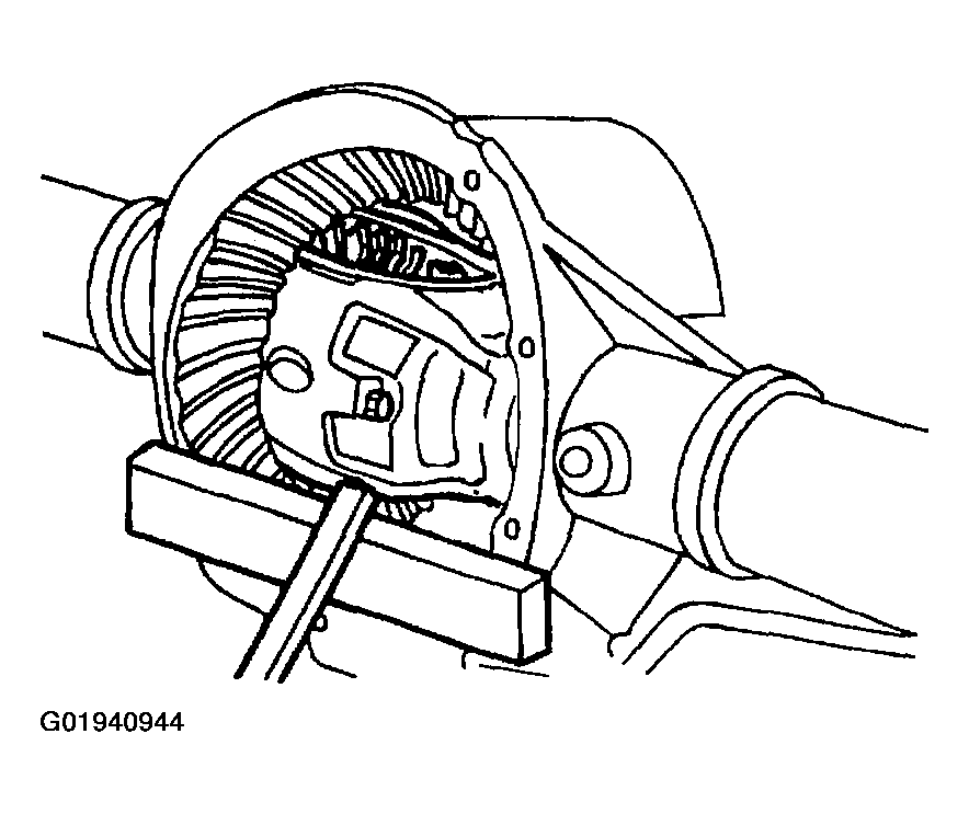
- Using a pry bar and a wood block, remove the differential assembly from the differential housing.
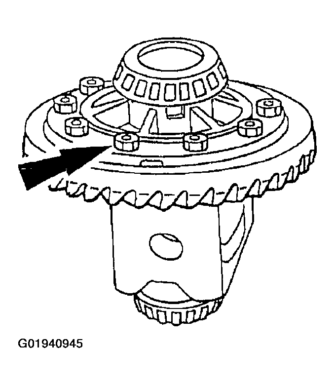
- Remove the bolts.
- Insert a punch in the bolt holes, and drive off the differential ring gear.
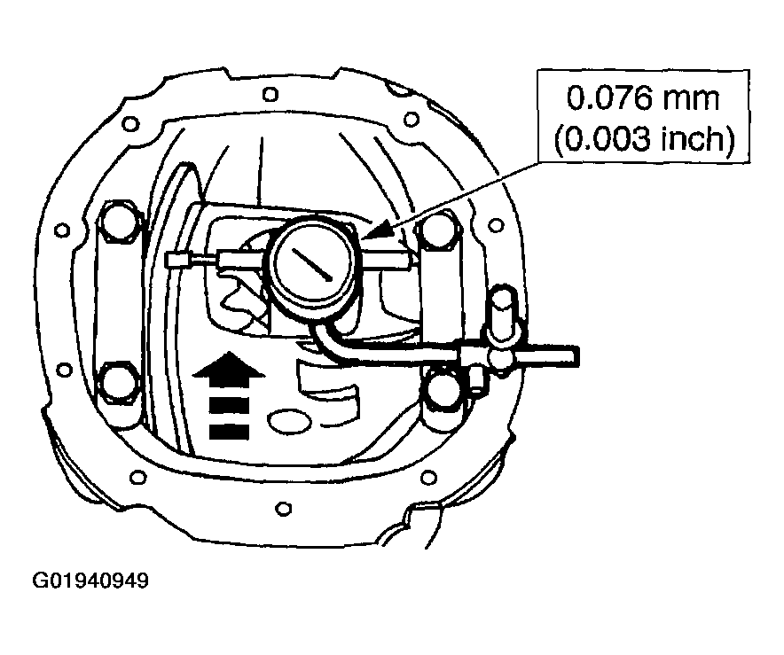
- If the differential ring gear backface runout measurement, taken at the beginning of this procedure, did not exceed the specification, proceed to the appropriate procedure as necessary: DRIVE PINION , DIFFERENTIAL CASE & RING GEAR - CONVENTIONAL or DIFFERENTIAL CASE & RING GEAR - TRACTION-LOK® in this section, or to Installation in this procedure. If the differential ring gear backface runout measurement, taken at the beginning of this procedure, exceeded the specification, the cause may be a warped differential ring gear, differential case/differential bearing damage. Proceed as follows to verify the cause of the excessive runout.
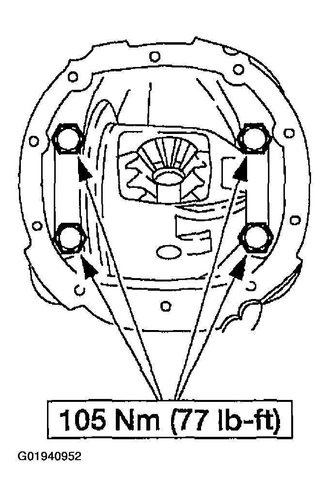
- Position the differential assembly, including the differential bearing cups (4222) and differential bearing shims (4067), in the differential housing. Install the differential bearing caps and the bolts.
- Position the special tool.
- Rotate the differential case to verify that the differential bearings (4221) have seated correctly.
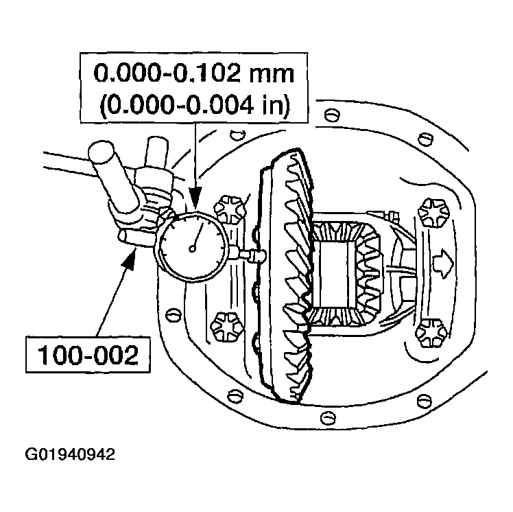
- Position the special tool.
- Measure and note the differential case runout.
- If the runout does not exceed the specification, install a new differential ring gear and pinion. For additional information, refer to DRIVE PINION and to INSTALLATION in this procedure.
- If the runout exceeds the specification, the differential ring gear is true and the concern is due to either differential case/differential bearing damage. Proceed as follows.
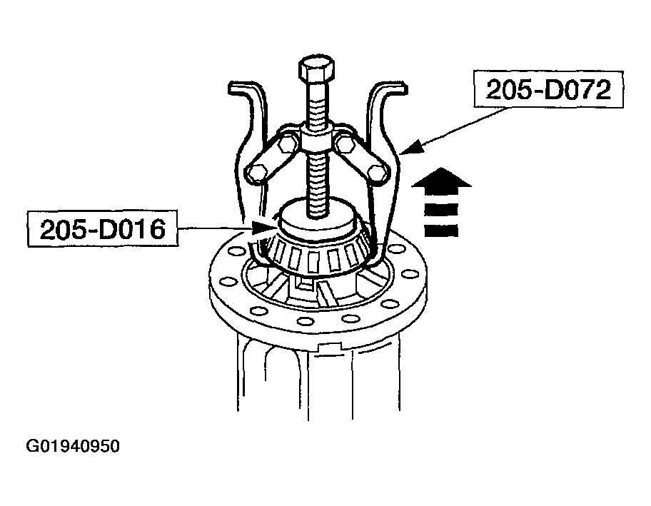
- Using the special tools, remove the differential bearings.
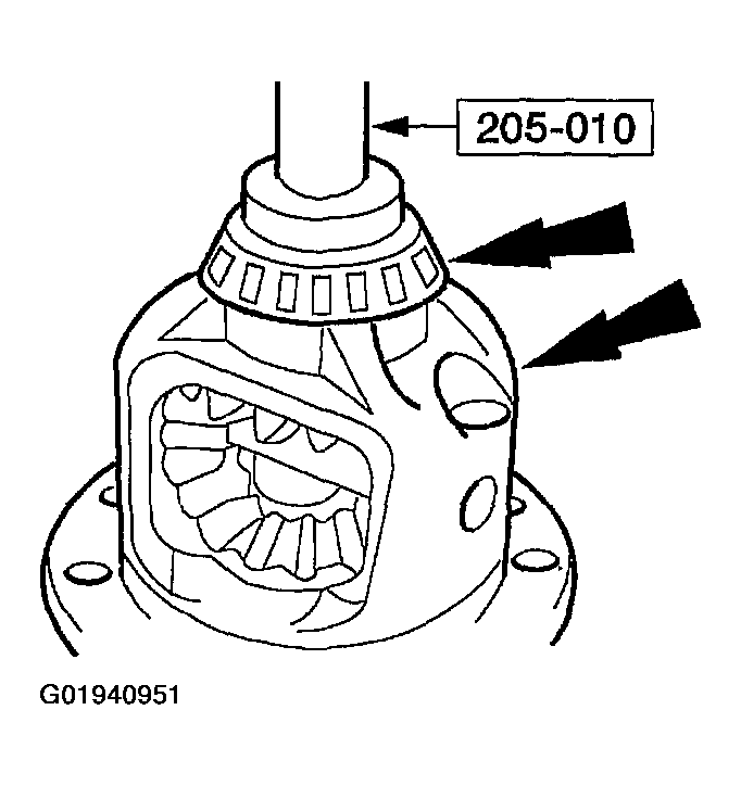
- Using the special tool, install the new differential bearings.
- Position the differential assembly, including the differential bearing cups and differential bearing shims in the differential housing. Tighten differential bearing caps to specification.
- Position the special tool.
- Rotate the differential case to verify that the differential bearings have seated correctly.
- Position the special tool.
- Measure the differential case runout.
- If the runout does not exceed the specification, use the new differential bearings for assembly.
- If the runout exceeds the specification, install a new differential case. For additional information, refer to DIFFERENTIAL CASE & RING GEAR - CONVENTIONAL or DIFFERENTIAL CASE & RING GEAR - TRACTION-LOK® in this section.
CAUTION:
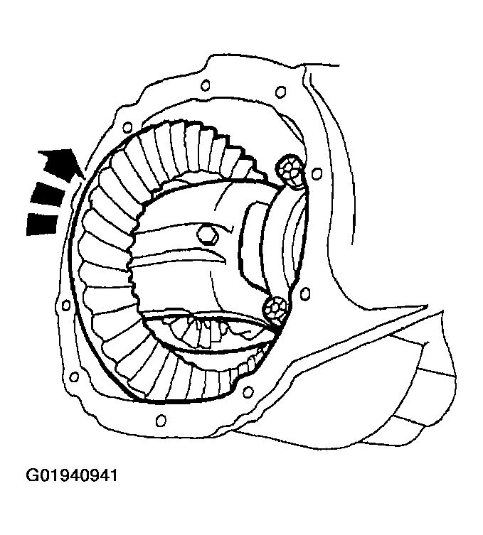
Mark the position of the differential bearing caps, as the arrows may not be visible. Always install the bearing caps in their identical locations and positions.
WARNING:
Do not allow the differential assembly to fall.
CAUTION:
Place a wood block between the pry bar and the differential housing (4010) to protect the machined surface from damage.
CAUTION:
Do not damage the differential ring gear bolt hole threads.