Test QA: Unable To Activate Self-Test/SCP Communication Error/DTC Not Listed: Testing
WARNING: This page is about a different variant/trim than selected.
NOTE:
Proceed to DTC testing steps listed in FAULT CODE SETTING CONDITION table of fault code setting condition.
FAULT CODE SETTING CONDITION
| Fault Code | KOEO | KOER | Continuous Memory |
|---|---|---|---|
| P1001 | QA1 |
- 1) KOER DTC P1001: Verify Self-Test Procedure
This test addresses the following:- KOEO or KOER self-test is unable to be activated.
- Unable to access Continuous Memory DTCs.
- Scan tool communication concern.
- DTC displayed by scan tool not listed.
- Power Take Off (PTO), if equipped.
- DTC P1001 KOER Self-Test cannot be completed.
Possible causes are:
- Damaged DLC.
- Incorrect self-test procedure.
- VREF is not within specification.
- Idle RPM out of specification.
- Open in DLC harness circuit.
- Short in DLC harness circuit or associated modules.
- Damaged PCM power relay circuit.
- Damaged PCM.
- PTO circuit, if equipped.
Ensure scan tool connector and DLC, located under dash panel, are not damaged or defective. Ensure scan tool is correctly attached to DLC. If equipped, ensure PTO switch/actuator is in OFF position. Verify correct procedure was used to activate Continuous Memory, KOEO or KOER self-test. If proper self-test procedure was performed, go to next step. If proper self-test was not performed, refer to procedures under QUICK TEST .
- 2) Check VREF Voltage To Throttle Position Sensor
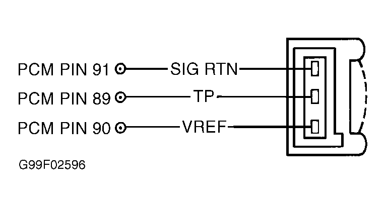
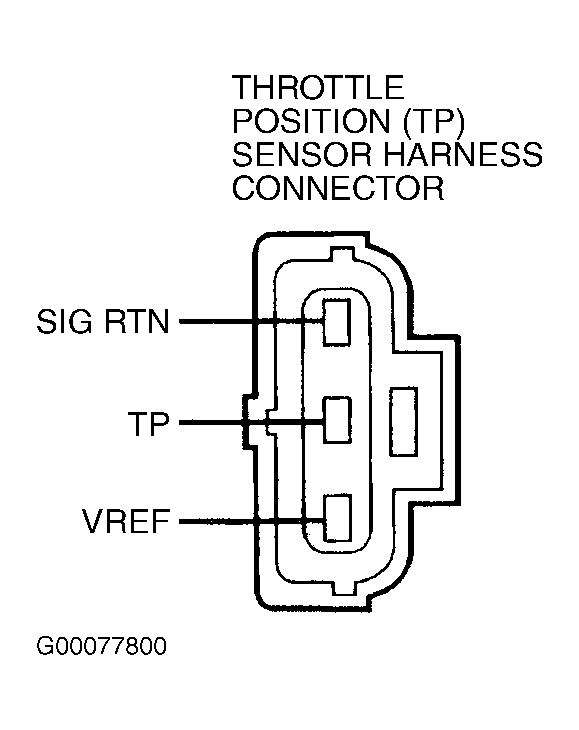
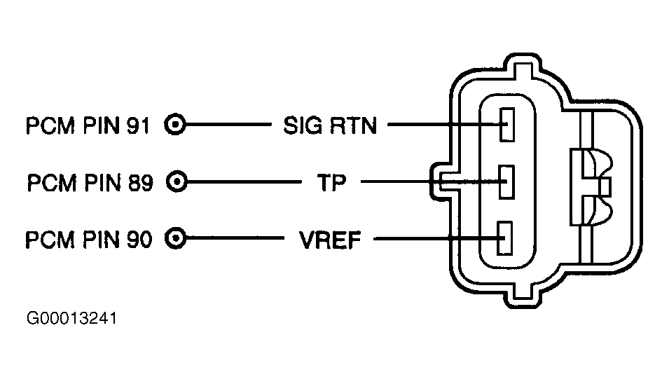
Turn ignition switch to OFF position. Disconnect Throttle Position (TP) sensor. Turn ignition switch to ON position. Using a DVOM, measure voltage between TP harness connector SIG RTN and VREF circuit terminals. See Fig 1 - Fig 5 . If voltage is 4-6 volts, voltage is within specification. Go to next step. If voltage is not 4-6 volts, voltage is not within specification. Reconnect TP sensor and go to TEST C, step 1) . - 3) Check Link Communication With TP Sensor Disconnected
Ensure TP sensor is disconnected. Connect scan tool to DLC. Turn ignition switch to ON position. Using scan tool, access TP V PID from PID/DATA MONITOR & RECORD menu. If TP V PID is not accessible, go directly to next step. If TP V PID is accessible, reconnect TP sensor while observing TP V PID. If scan tool communication error occurs only when TP sensor is reconnected, VREF circuit is shorted to SIG RTN circuit in TP sensor. Replace TP sensor. If no scan tool communication error occurs, go to next step. - 4) Ability To Access Continuous Memory DTCs
If Continuous Memory DTCs are accessible, go to next step. If Continuous Memory DTCs are not accessible, turn ignition switch to OFF position and go to step 8). - 5) Ability To Activate KOEO Self-Test
If KOEO self-test can be activated, go to next step. If KOEO self-test cannot be activated, go to step 7). - 6) Ability To Activate KOER Self-Test
If KOER self-test cannot be activated or completed, go to next step. If KOER self-test can be activated and you were directed here to diagnose DTC P1001 and other KOER DTCs are present, go to DIAGNOSTIC TROUBLE CODE DEFINITIONS and service DTCs in order retrieved. If DTC retrieved is not listed in DIAGNOSTIC TROUBLE CODE DEFINITIONS, obtain PCM part number and ensure correct PCM is installed for application. Also, check Technical Service Bulletins (TSBs) or manufacturer for PCM changes or calibration (Flash Vehicle Identification Block) updates. - 7) Retrieve Any Continuous Memory DTCs
Perform CONTINUOUS MEMORY SELF-TEST under QUICK TEST. If any Continuous Memory DTCs are present, service DTCs as necessary before continuing. See DIAGNOSTIC TROUBLE CODE DEFINITIONS . If unable to retrieve any Continuous Memory DTCs, go to next step. - 8) Check B+ Voltage To Data Link Connector
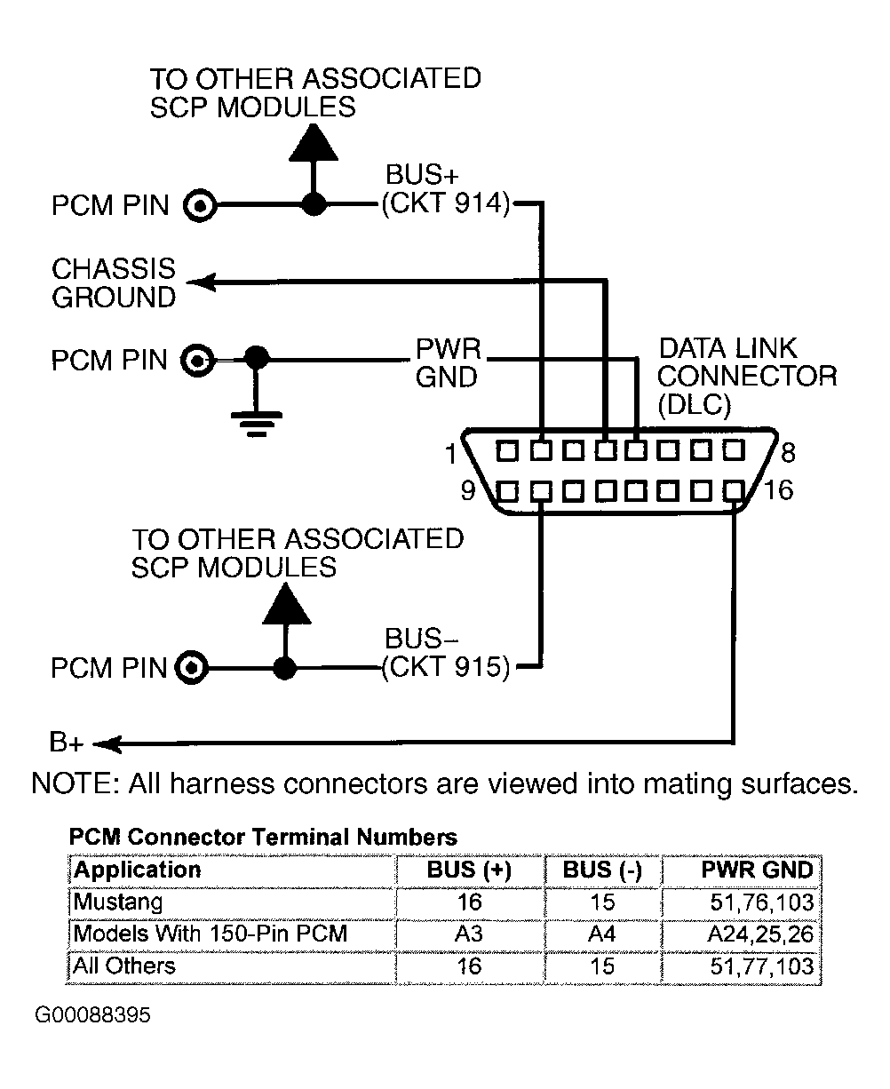
Disconnect scan tool from DLC. Inspect DLC for damage and repair as necessary. Using a DVOM, measure voltage between chassis ground and DLC terminal No. 16 (B+). See Figure. If voltage is more than 10.5 volts, go to next step. If voltage is 10.5 volts or less, repair open in DLC B+ circuit. - 9) Check DLC CHASSIS GROUND Circuit For Open In Harness
Turn ignition switch to OFF position. Using a DVOM, measure resistance between negative battery terminal and DLC terminal No. 4 (CHASSIS GND). If resistance is less than 5 ohms, go to next step. If resistance is 5 ohms or more, repair open in CHASSIS GND circuit to DLC. - 10) Check DLC PWR GND Circuit For Open In Harness
Ensure ignition switch is turned to OFF position. Using a DVOM, measure resistance between negative battery terminal and DLC terminal No. 5 (PWR GND). If resistance is less than 5 ohms, go to next step. If resistance is 5 ohms or more, repair open in PWR GND circuit to DLC. - 11) Perform Data Link Diagnostic Network Test
Connect scan tool to DLC. Turn ignition switch to ON position. If scan tool does not have DATA LINK DIAGNOSTIC NETWORK TEST capability, go directly to step 22). Using scan tool, perform DATA LINK DIAGNOSTICS. If either PCM: NO RESPONSE/NOT EQUIPPED, PCM: NO RESPONSE CKT 914BUS (+) or PCM: NO RESPONSE CKT 915BUS (-) message is displayed, go to next step. If specified messages are not displayed, no concern is indicated at this time. Repeat QUICK TEST . - 12) Network Test Results: Circuit 914BUS (+) & Circuit 915BUS (-)
Proceed as follows for appropriate message displayed:- If only BUS(+) CKT 914=ALL MODULE NO RESP/NOT EQUIP message is displayed, go to next step.
- If only BUS(-) CKT 915=ALL MODULE NO RESP/NOT EQUIP message is displayed, go to step 16).
- If both BUS(+) CKT 914 and BUS(-) CKT 915=ALL MODULE NO RESP/NOT EQUIP messages are displayed, go to step 22).
- If BUS(+) CKT 914=SOME MODULE NO RESP/NOT EQUIP or PCM: NO RESPONSE ON BUS(+) CKT 914 message is displayed, go to step 15).
- If BUS(-) CKT 915=SOME MODULE NO RESP/NOT EQUIP or PCM: NO RESPONSE ON BUS(-) CKT 915 message is displayed, go to step 18).
- If both BUS(+) CKT 914 and BUS(-) CKT 915=SOME MODULE NO RESP/NOT EQUIP or PCM: NO RESPONSE ON BUS(+) & BUS(-) messages are displayed, go to step 23).
- 13) Check BUS(+) CKT 914 For Short To Ground In Harness
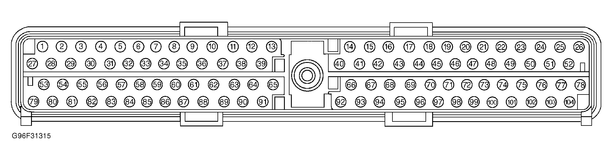
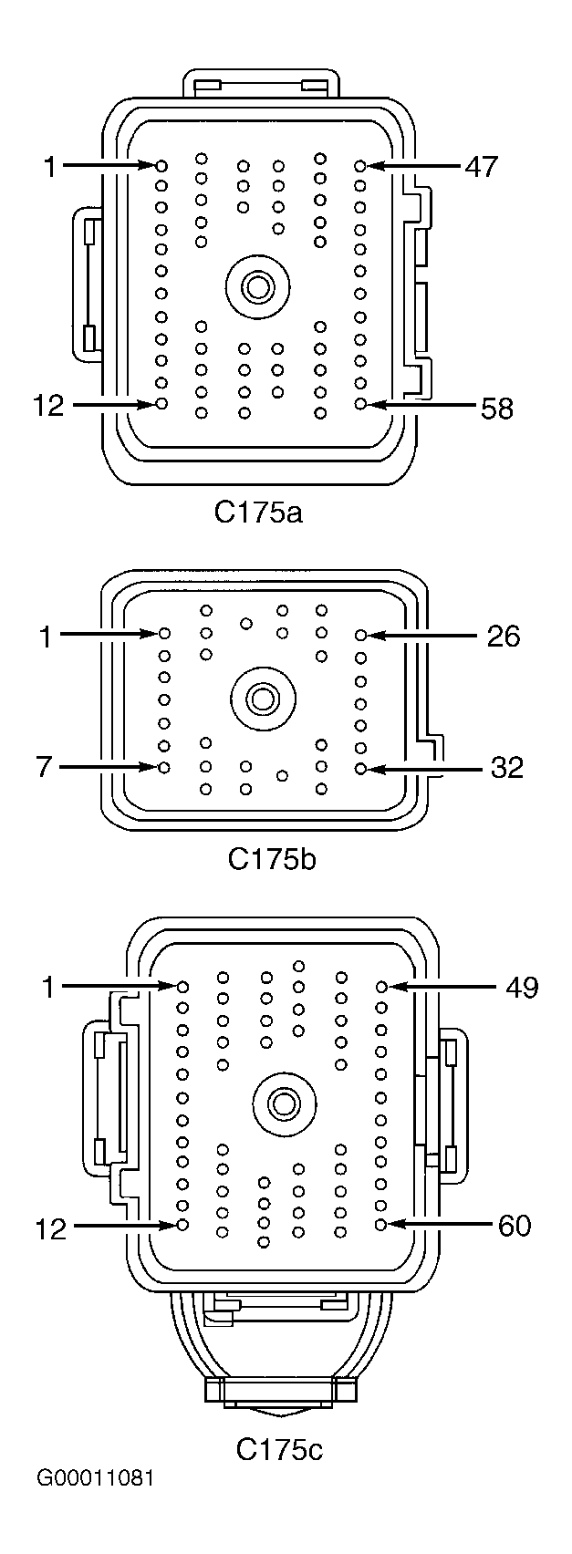
Turn ignition switch to OFF position. Disconnect PCM connector(s). Inspect connector for loose, damaged or corroded terminals. Repair as necessary. Using a DVOM, measure resistance of BUS(+) CKT 914 circuit between chassis ground and PCM harness connector. See Figure, Figure and Figure . If resistance is more than 50 ohms, go to next step. If resistance is 50 ohms or less, repair short to ground in BUS(+) CKT 914 circuit or associated modules. See appropriate MODULE COMMUNICATIONS NETWORK article in ACCESSORIES & EQUIPMENT for further diagnosis. - 14) Check BUS(+) CKT 914 For Short To B+ In Harness
Turn ignition switch to ON position. Using a DVOM, measure voltage between chassis ground and BUS(+) CKT 914 circuit at PCM harness connector. If voltage is one volt or less, go to next step. If voltage is more than one volt, repair short to B+ in BUS(+) CKT 914 circuit or associated modules. See appropriate MODULE COMMUNICATIONS NETWORK article in ACCESSORIES & EQUIPMENT for further diagnosis. - 15) Check DLC BUS(+) CKT 914 For Open In Harness
Turn ignition switch to OFF position and disconnect PCM connector(s), if not done previously. Using a DVOM, measure resistance of BUS(+) CKT 914 circuit between PCM harness connector and DLC. See Figure, Figure and Figure . If resistance is less than 5 ohms, go to next step. If resistance is 5 ohms or more, repair open in BUS(+) CKT 914 circuit to DLC. - 16) Check BUS(-) CKT 915 For Short To Ground In Harness
Disconnect PCM if not done previously. Using a DVOM, measure resistance of BUS(-) CKT 915 circuit between PCM harness connector and negative battery terminal. If resistance is more than 50 ohms, go to next step. If resistance is 50 ohms or less, repair short to ground in BUS(-) CKT 915 circuit or associated modules. See appropriate MODULE COMMUNICATIONS NETWORK article in ACCESSORIES & EQUIPMENT for further diagnosis. - 17) Check BUS(-) CKT 915 For Short To B+ In Harness
Turn ignition switch to ON position. Using a DVOM, measure voltage between chassis ground and BUS(-) CKT 915 circuit at PCM harness connector. See Figure, Figure and Figure . If voltage is 6 volts or less, go to next step. If voltage is more than 6 volts, repair a short to B+ in BUS(-) CKT 915 circuit or associated modules. See appropriate MODULE COMMUNICATIONS NETWORK article in ACCESSORIES & EQUIPMENT for further diagnosis. - 18) Check DLC BUS(-) CKT 915 For Open In Harness
Turn ignition switch to OFF position. Using a DVOM, measure resistance of BUS(-) CKT 915 between PCM harness connector and DLC. See Figure, Figure and Figure . If resistance is less than 5 ohms, go to next step. If resistance is 5 ohms or more, repair open in BUS(-) CKT 915 circuit to DLC. - 19) Check Power Relay VPWR To PCM
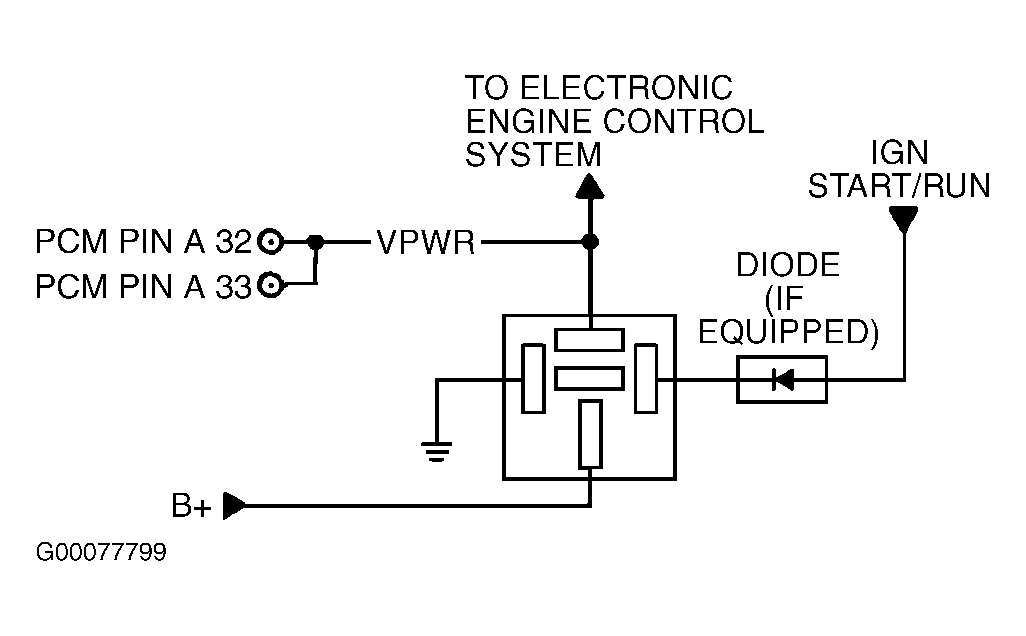
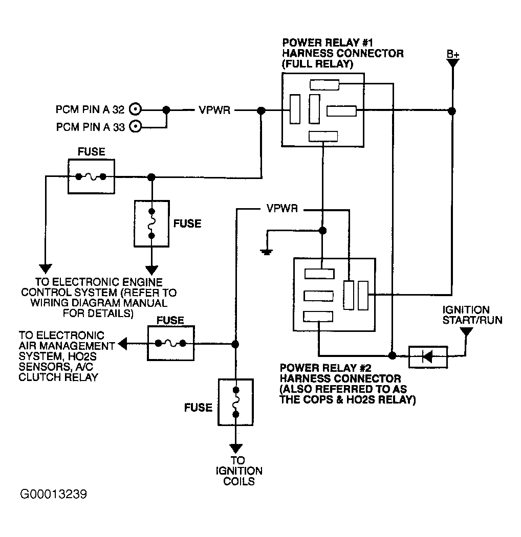
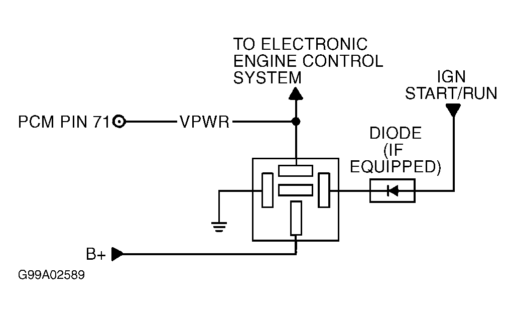
Turn ignition switch to OFF position. Disconnect PCM connector(s). Turn ignition switch to ON position. Using a DVOM, measure voltage between VPWR and GND circuits at PCM harness connector. See Figure, Figure and Fig 6 - Fig 9 . See PCM PWR GND, SIG RTN & VREF TERMINAL IDENTIFICATION table. If voltage is 10.5 volts or less, turn ignition switch to OFF position. Repair VPWR circuit from PCM power relay to PCM. If voltage is more than 10.5 volts, go to next step (for scan tools with Data Link Diagnostic Network Test capability), or for scan tools without Data Link Diagnostic Network Test capability, see appropriate MODULE COMMUNICATIONS NETWORK article in ACCESSORIES & EQUIPMENT for further diagnosis. If after completing MODULE COMMUNICATIONS NETWORK diagnosis and you are directed back here, replace PCM.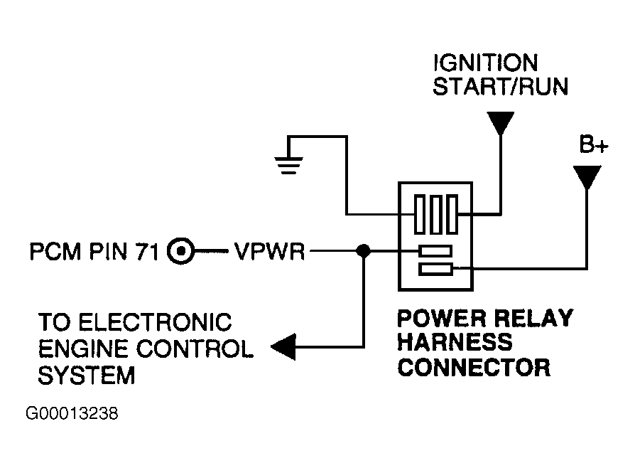 Courtesy of FORD MOTOR CO.
- 20) Power Take Off Applications
If vehicle is equipped with Power Take Off (PTO), go to next step. If vehicle is not equipped with PTO, replace PCM. - 21) Check PTO ON/OFF Input
Turn ignition switch to ON position. While cycling PTO switch/actuator, measure voltage between chassis ground and PTO circuit at PCM harness connector terminal No. 4. If voltage is more than one volt with PTO on, and less than one volt with PTO off, PTO circuit is okay. Replace PCM. If voltage is not as specified, PTO circuit has a fault. Go to TEST FB, step 1) for PTO circuit fault diagnosis. - 22) Check For BUS(+) CKT 914 Shorted To BUS(-) CKT 915
Turn ignition switch to OFF position. Disconnect PCM connector(s). Using a DVOM, measure resistance between BUS(+) CKT 914 and BUS(-) CKT 915 circuits at PCM harness connector. See Figure, Figure and Figure . If resistance is more than 5 ohms, go to next step. If resistance is 5 ohms or less, repair short between BUS(+) CKT 914 and BUS(-) CKT 915 circuits or in associated modules. See appropriate MODULE COMMUNICATIONS NETWORK article in ACCESSORIES & EQUIPMENT for further diagnosis. - 23) Check For Open BUS(+) CKT 914 Or BUS(-) CKT 915 In Harness
Using a DVOM, measure resistance of BUS(+) CKT 914 and BUS(-) CKT 915 circuits between PCM harness connector and DLC. See Figure, Figure and Figure . If either resistance is 5 ohms or more, repair open in BUS(+) CKT 914 or BUS(-) CKT 915 between DLC and all associated modules. If both resistance measurements are less than 5 ohms, go to step 19) (if scan tool has DATA LINK DIAGNOSTIC NETWORK TEST capability, or if scan tool does not have DATA LINK DIAGNOSTIC NETWORK TEST capability, see appropriate MODULE COMMUNICATIONS NETWORK article in ACCESSORIES & EQUIPMENT for further diagnosis. If MODULE COMMUNICATIONS NETWORK article diagnostics are completed and you are directed back to SELF-DIAGNOSTICS - EEC-V - GASOLINE & NGV article, replace PCM.
NOTE:
For additional testing information, see DIAGNOSTIC AIDS .
NOTE:
Loss of VREF caused by an open, or short to PWR or GND, can cause an SCP communication error, or an unable to complete self-test concern.
Fig 1: Identifying TP Sensor Circuits & Connector Terminals - Cougar & Escort 2.0L (4V) - Early Production
 Courtesy of FORD MOTOR CO.
Fig 2: Identifying TP Sensor Circuits & Connector Terminals - Cougar & Escort 2.0L (4V) - Late Production
 Courtesy of FORD MOTOR CO.
 Courtesy of FORD MOTOR CO.
Fig 4: Identifying TP Sensor Circuits & Connector Terminals - Explorer, LS, Mountaineer & Thunderbird
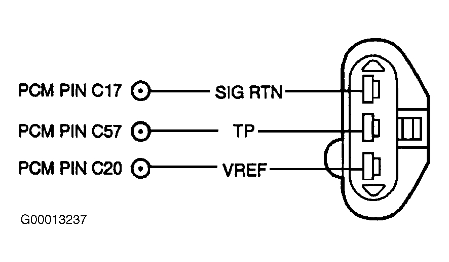 Courtesy of FORD MOTOR CO.
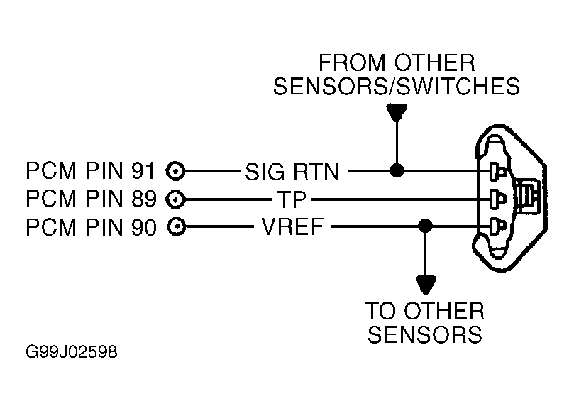
NOTE:
Faults in idle speed control, EGR system, fuel control system, electronic secondary air system, Vehicle Speed Sensor (VSS) circuits, Mass Airflow (MAF) sensor circuits or Transmission Range (TR) sensor circuits can cause self-test to be incomplete or scan tool to display communication error message.