DTC B1825: Slide Pulse Error(No Change in Pulse for 1 Second)
| DTC Description | DTC |
|---|---|
| B1825 Slide Pulse Error(No Change in Pulse for 1 Second) |
NOTE:
- If you are troubleshooting multiple DTCs, be sure to follow the instructions in B-CAN System Diagnosis Test Mode A - Refer to: Body Electrical Troubleshooting - B-CAN System Diagnosis Test Mode A - Initial Communication and DTC ChecksBody Electrical Troubleshooting - B-CAN System Diagnosis Test Mode 1 and Test Mode 2 (without the HDS)Body Electrical Troubleshooting - B-CAN System Diagnosis Test Mode B - Control Unit Not CommunicatingBody Electrical Troubleshooting - B-CAN System Diagnosis Test Mode C - No DTCs and Output Won't Shut OFFBody Electrical Troubleshooting - B-CAN System Diagnosis Test Mode D - No DTCs and Output Won't Turn ON .
- If DTC B1825 and B1826 are both indicated, check for a blown No. B16 (20 A) fuse in the under-dash fuse/relay box. If the fuse blows again, check for a short to ground in the slide motor circuit.
- 1. Problem verification:
1. Clear the DTCs with the HDS.
2. Press the engine start/stop button at least 20 times, then wait for at least 20 seconds.
3. Operate the power seat adjustment switch for several seconds in each direction.
NOTE: DTC B1825 is stored when the slide switch is operated more than 1 second after the seat moves to the most forward or backward position, even when the system is OK.
4. Check for DTCs with the HDS.
DTC Description DTC B1825 Slide Pulse Error(No Change in Pulse for 1 Second) Is DTC B1825 indicated?
DTC B1825 is indicated
Go to step 2.
DTC B1836 is also indicated
Go to the DTC B1836 troubleshooting.
DTC B1826, B1827, and/or B1828 are also indicated
Go to step 6.
NO
Intermittent failure, the system is OK at this time. Check for loose or poor connections.
- 2. Determine possible failure area (motor operation, motor sensor):
1. Turn the vehicle to the OFF (LOCK) mode and then the ON mode.
2. Operate the slide switch for 2 seconds, and check the slide motor operation.
Does the slide motor run smoothly?
YES
Go to step 3.
NO
Go to step 8.
- 3. Open wire check (SLSE, SEG lines):
1. Turn the vehicle to the OFF (LOCK) mode and then the ON mode.
2. Disconnect the following connectors.
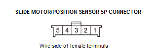
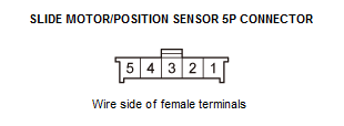
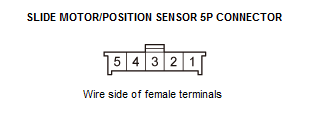
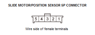
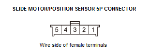
Slide motor/position sensor 5P connector Power seat control unit connector B (40P) 3. Check for continuity between test points 1 and 2 respectively.
Test condition Vehicle OFF (LOCK) mode Slide motor/position sensor 5P connector: disconnected
Power seat control unit connector B (40P): disconnected
Test point 1 Slide motor/position sensor 5P connector No. 2 Test point 2 Power seat control unit connector B (40P) No. 10 Test point 1 Slide motor/position sensor 5P connector No. 3 Test point 2 Power seat control unit connector B (40P) No. 32 Is there continuity?
YES
The SLSE and SEG wires are not open. Go to step 4.
NO
Repair an open or high resistance in the wire.
- 4. Shorted wire check (SLSE line):
1. Check for continuity between test points 1 and 2.
Test condition Vehicle OFF (LOCK) mode Slide motor/position sensor 5P connector: disconnected
Power seat control unit connector B (40P): disconnected
Test point 1 Power seat control unit connector B (40P) No. 10 Test point 2 Body ground Is there continuity?
YES
Repair a short to ground in the wire.
NO
The SLSE wire is not shorted. Go to step 5.
- 5. Slide position sensor check:
1. Reconnect power seat control unit connector B (40P).
2. Turn the vehicle to the ON mode.
3. Measure the voltage between test points 1(+) and 2(-).
Test condition Vehicle ON mode Slide motor/position sensor 5P connector: disconnected
Test point 1 Slide motor/position sensor 5P connector No. 2 (+) Test point 2 Slide motor/position sensor 5P connector No. 3 (-) Is there about 5 V?
About 5 V
Faulty slide motor/position sensor; replace the slide motor/position sensor .
No voltage
Replace the power seat control unit .
Battery voltage
Repair a short to power in the wire (sensor line).
- 6. Open wire check (SVCC, SEG lines):
1. Turn the vehicle to the OFF (LOCK) mode.
2. Disconnect the following connectors.
Slide motor/position sensor 5P connector Power seat control unit connector B (40P) 3. Check for continuity between test points 1 and 2 respectively.
Test condition Vehicle OFF (LOCK) mode Slide motor/position sensor 5P connector: disconnected
Power seat control unit connector B (40P): disconnected
Test point 1 Slide motor/position sensor 5P connector No. 4 Test point 2 Power seat control unit connector B (40P) No. 6 Test point 1 Slide motor/position sensor 5P connector No. 3 Test point 2 Power seat control unit connector B (40P) No. 32 Is there continuity?
YES
The SVCC and SEG wires are OK. Go to step 7.
NO
Repair an open or high resistance in the wire.
- 7. Power seat control unit check:
1. Reconnect power seat control unit connector B (40P).
2. Turn the vehicle to the ON mode.
3. Measure the voltage between test points 1 and 2.
Test condition Vehicle ON mode Slide motor/position sensor 5P connector: disconnected
Test point 1 Power seat control unit connector B (40P) No. 6 Test point 2 Power seat control unit connector B (40P) No. 32 Is there battery voltage when the slide switch is operated?
YES
Faulty slide motor/position sensor; replace the slide motor/position sensor .
NO
- 8. Fuse check:
1. Turn the vehicle to the OFF (LOCK) mode.
2. Check the following fuse.
Fuse No. B16 (20 A) Location Under-dash fuse/relay box Is the fuse OK?
YES
Go to step 9.
NO
Replace the fuse. If the fuse blows again, repair the short to ground in the No. B16 (20 A) fuse circuit.
- 9. Open wire check (+B P/SEAT HT/SLI(20A) line):
1. Measure the voltage between test points 1 and 2.
Test condition Vehicle OFF (LOCK) mode Test point 1 Power seat control unit connector A (18P) No. 1 Test point 2 Body ground Is there battery voltage?
YES
The +B P/SEAT HT/SLI(20A) wire is not open. Go to step 10.
NO
Repair an open or high resistance in the wire.
- 10. Open wire check (PG1 line):
1. Measure the voltage between test points 1 and 2.
Test condition Vehicle OFF (LOCK) mode Test point 1 Power seat control unit connector A (18P) No. 9 Test point 2 Body ground Is there 0.2 V or more?
YES
Repair an open or high resistance in the ground wire or poor ground (G601).
NO
The PG1 wire is not open. Go to step 11.
- 11. Open wire check (SLIDE MTR FR, SLIDE MTR RR lines):
1. Disconnect the following connectors.
Slide motor/position sensor 5P connector Power seat control unit connector A (18P) 2. Check for continuity between test points 1 and 2 respectively.
Test condition Vehicle OFF (LOCK) mode Slide motor/position sensor 5P connector: disconnected
Power seat control unit connector A (18P): disconnected
Test point 1 Slide motor/position sensor 5P connector No. 5 Test point 2 Power seat control unit connector A (18P) No. 10 Test point 1 Slide motor/position sensor 5P connector No. 1 Test point 2 Power seat control unit connector A (18P) No. 2 Is there continuity?
YES
The SLIDE MTR FR and SLIDE MTR RR wires are not open. Go to step 12.
NO
Repair an open or high resistance in the wire.
- 12. Shorted wire check (SLIDE MTR FR, SLIDE MTR RR lines):
1. Check for continuity between test points 1 and 2 individually.
Test condition Vehicle OFF (LOCK) mode Slide motor/position sensor 5P connector: disconnected
Power seat control unit connector A (18P): disconnected
Test point 1 Slide motor/position sensor 5P connector No. 5 Test point 2 Body ground Test point 1 Slide motor/position sensor 5P connector No. 1 Test point 2 Body ground Is there continuity?
YES
Repair a short to ground in the wire.
NO
The SLIDE MTR FR and SLIDE MTR RR wires are OK. Go to step 13.
- 13. Slide motor check:
1. Test the slide motor .
Is the motor OK?
YES
Replace the power seat control unit .
NO