Reminder Systems (MICU and Gauge Control Module) Input Test
NOTE:
- If you are troubleshooting multiple DTCs, be sure to follow the instructions in B-CAN System Diagnosis Test Mode A - Refer to: Body Electrical Troubleshooting - B-CAN System Diagnosis Test Mode A - Initial Communication and DTC ChecksBody Electrical Troubleshooting - B-CAN System Diagnosis Test Mode 1 and Test Mode 2 (without the HDS)Body Electrical Troubleshooting - B-CAN System Diagnosis Test Mode B - Control Unit Not CommunicatingBody Electrical Troubleshooting - B-CAN System Diagnosis Test Mode C - No DTCs and Output Won't Shut OFFBody Electrical Troubleshooting - B-CAN System Diagnosis Test Mode D - No DTCs and Output Won't Turn ON .
- Before testing, do the gauge control module self-diagnostic function to make sure the beeper and the indicators in the gauge control module work properly and the F-CAN line are OK.
- Before testing, make sure the No. A29 (10 A) fuse in the under-hood fuse/relay box is OK.
- Before testing, make sure the No. B5 (10 A) fuse in the under-dash fuse/relay box is OK.
MICU
1. Turn the vehicle to the OFF (LOCK) mode
2. Disconnect the following connectors.
| Under-dash fuse/relay box connector B (44P) |
| Under-dash fuse/relay box connector D (32P) |
| Under-dash fuse/relay box connector P (20P) |
| Under-dash fuse/relay box connector T (20P) |
| Under-dash fuse/relay box connector W (24P) |
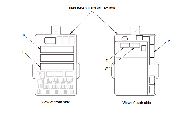
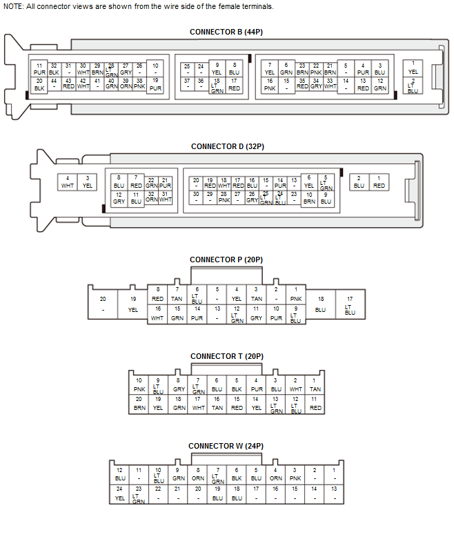
3. Inspect the connectors and socket terminals to be sure they are all making good contact:
- If the terminals are bent, loose, or corroded, repair them as necessary, and recheck the system.
- If the terminals are OK, go to step 4.
4. With the connectors still disconnected, do the following input tests:
- If any test indicates a problem, find and correct the cause, then recheck the system.
- If all the input tests prove OK, go to step 5.
| Cavity | Wire | Test condition | Test: Desired result | Possible cause if desired result is not obtained |
|---|---|---|---|---|
| P11* | GRY | Disconnect the keyless access control unit connector C (24P) | Check for continuity between terminal P11 and keyless access control unit connector C (24P) terminal No. 6: There should be continuity. | An open or high resistance in the wire |
*: With keyless access system
5. Reconnect the connectors to the under-dash fuse/relay box, and do the following input tests:
- If any test indicates a problem, find and correct the cause, then recheck the system.
- If all the input tests prove OK, go to step 6.
| Cavity | Wire | Test condition | Test: Desired result | Possible cause if desired result is not obtained |
|---|---|---|---|---|
| D17 | RED | Under all conditions | Measure the voltage to ground: There should be battery voltage. |
|
| W6 | BLK | In all ignition switch positions or all power modes | Measure the voltage to ground: There should be less than 0.2 V. |
|
| B32 | BLK | In all ignition switch positions or all power modes | Measure the voltage to ground: There should be less than 0.2 V. |
|
| B20 | BLK | In all ignition switch positions or all power modes | Measure the voltage to ground: There should be less than 0.2 V. |
|
| D10 | BRN | In all ignition switch positions or all power modes | Measure the voltage to ground: There should be less than 0.2 V. |
|
| B40 | GRN | Driver's door open | Measure the voltage to ground: There should be less than 0.2 V. |
|
| Driver's door closed | Measure the voltage to ground: There should be about 5 V. |
|
||
| B29 | BRN | Front passenger's door open | Measure the voltage to ground: There should be less than 0.2 V. |
|
| Front passenger's door closed | Measure the voltage to ground: There should be about 5 V. |
|
*1: Without power tailgate*2: With power tailgate*3: Without keyless access system
| Cavity | Wire | Test condition | Test: Desired result | Possible cause if desired result is not obtained |
|---|---|---|---|---|
| B33 | WHT | Left rear door open | Measure the voltage to ground: There should be less than 0.2 V. |
|
| Left rear door closed | Measure the voltage to ground: There should be about 5 V. |
|
||
| B34 | GRY | Right rear door open | Measure the voltage to ground: There should be less than 0.2 V. |
|
| Right rear door closed | Measure the voltage to ground: There should be about 5 V. |
|
||
| B22 | PNK | Tailgate open | Measure the voltage to ground: There should be less than 0.2 V. |
|
| Tailgate closed | Measure the voltage to ground: There should be about 5 V. |
|
||
| P11*3 | GRY | Ignition key inserted into the ignition key cylinder | Measure the voltage to ground: There should be less than 0.2 V. |
|
| Ignition key removed from the ignition key cylinder | Measure the voltage to ground: There should be about 5 V. |
|
||
| T1. T5 | TAN. BLK | Combination light switch OFF | Measure the voltage between terminals T1 and T5: There should be less than 0.2 V. |
|
| Combination light switch in any position other than OFF | Measure the voltage between terminals T1 and T5: There should be about 5 V. |
|
||
| T3. T5 | BLU. BLK | Combination light switch (PARKING position) ON | Measure the voltage between terminals T3 and T5: There should be less than 0.2 V. |
|
| Combination light switch OFF | Measure the voltage between terminals T3 and T5: There should be about 5 V. |
|
||
| T2. T5 | WHT. BLK | Combination light switch (headlight) ON | Measure the voltage between terminals T2 and T5: There should be less than 0.2 V. |
|
| Combination light switch OFF | Measure the voltage between terminals T2 and T5: There should be about 5 V. |
|
*1: Without power tailgate*2: With power tailgate*3: Without keyless access system
Gauge Control Module
6. Turn the vehicle to the OFF (LOCK) mode
7. Disconnect the following connector.
| Gauge control module connector A (32P) |
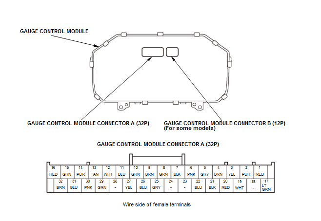
8. Inspect the connector and socket terminals to be sure they are all making good contact:
- If the terminals are bent, loose, or corroded, repair them as necessary, and recheck the system.
- If the terminals are OK, go to step 9.
9. Reconnect the connector, and do the following input tests:
- If any test indicates a problem, find and correct the cause, then recheck the system.
- If all the input tests prove OK, go to step 10.
| Cavity | Wire | Test condition | Test: Desired result | Possible cause if desired result is not obtained |
|---|---|---|---|---|
| A1 | RED | Under all conditions | Measure the voltage to ground: There should be battery voltage. |
|
| A17 | LT GRN | Vehicle ON mode | Measure the voltage to ground: There should be battery voltage. |
|
| Cavity | Wire | Test condition | Test: Desired result | Possible cause if desired result is not obtained |
|---|---|---|---|---|
| A4 | BRN | In all ignition switch positions or all power modes | Measure the voltage to ground: There should be less than 0.2 V. |
|
| A26 | BLU | Vehicle ON mode, parking brake pedal pressed | Measure the voltage to ground: There should be less than 0.2 V. |
|
| Vehicle ON mode, parking brake pedal released | Measure the voltage to ground: There should be battery voltage. |
|
10.If multiple failures are found on more than one control unit, replace the under-dash fuse/relay box (includes the MICU) . If input failures are related to a particular control unit, replace the gauge control module .