DTC B1660: Front Interior LF Antenna Circuit Open
| DTC Description | DTC |
|---|---|
| B1660 Front interior LF antenna circuit open |
NOTE: If you are troubleshooting multiple DTCs, be sure to follow the instructions in B-CAN System Diagnosis Test Mode A - Refer to: Body Electrical Troubleshooting - B-CAN System Diagnosis Test Mode A - Initial Communication and DTC ChecksBody Electrical Troubleshooting - B-CAN System Diagnosis Test Mode 1 and Test Mode 2 (without the HDS)Body Electrical Troubleshooting - B-CAN System Diagnosis Test Mode B - Control Unit Not CommunicatingBody Electrical Troubleshooting - B-CAN System Diagnosis Test Mode C - No DTCs and Output Won't Shut OFFBody Electrical Troubleshooting - B-CAN System Diagnosis Test Mode D - No DTCs and Output Won't Turn ON .
- 1. Problem verification:
1. Clear the DTCs with the HDS.
2. Select the KEYLESS ACCESS CONTROL UNIT from the ONE-PUSH START system select menu with the HDS, and enter the SELF CHECK.
3. Do the SELF CHECK.
4. Check for DTCs with the HDS.
DTC Description DTC B1660 Front interior LF antenna circuit open Is DTC B1660 indicated?
YES
Go to step 2.
NO
Intermittent failure, the system is OK at this time. Check for loose or poor connections.
- 2. Keyless access control unit EXT F+, EXT F- line output check:
1. Turn the vehicle to the OFF (LOCK) mode.
2. Disconnect the following connector.
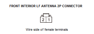
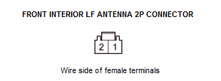
Front interior LF antenna 2P connector 3. Turn the vehicle to the ON mode.
4. Select KEYLESS ACCESS CONTROL from the ONE-PUSH START system select menu with the HDS, and enter FUNCTIONAL TESTS.
5. Connect the voltmeter between test points 1 and 2.
Test point 1 Front interior LF antenna 2P connector No. 1 Test point 2 Front interior LF antenna 2P connector No. 2 6. Select FRONT INTERIOR ANTENNA with the HDS.
Is there voltage?
YES
Replace the front interior LF antenna - Refer to: Keyless Access LF Antenna (Middle Interior) Removal and InstallationKeyless Access LF Antenna (Front Interior) Removal and InstallationKeyless Access LF Antenna (Rear Interior) Removal and InstallationKeyless Access LF Antenna (Rear Bumper) Removal and Installation .
NO
Go to step 3.
- 3. Open wire check (EXT F+, EXT F- lines):
1. Turn the vehicle to the OFF (LOCK) mode.
2. Disconnect the following connector.
Keyless access control unit connector A (32P) 3. Check for continuity between test points 1 and 2 respectively.
Test condition Vehicle OFF (LOCK) mode Keyless access control unit connector A (32P): disconnected
Front interior LF antenna 2P connector: disconnected
Test point 1 Keyless access control unit connector A (32P) No. 32 Test point 2 Front interior LF antenna 2P connector No. 2 Test point 1 Keyless access control unit connector A (32P) No. 16 Test point 2 Front interior LF antenna 2P connector No. 1 Is there continuity?
YES
The EXT F+ and EXT F- wires are OK. Replace the keyless access control unit .
NO
Repair an open or high resistance in the wire.