Removal And Installation: Installation
WARNING: This page is about a different variant/trim than selected.
- Place commercially available rubber spacer blocks, such as ROTFJ2427/J2440 or equivalent, on the (special tool #BX50-CHR, Table, Bishamon Lift) and position it under the powertrain and suspension crossmember assembly.
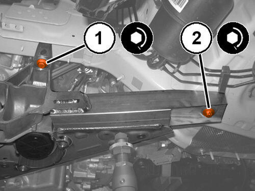
- Tighten the NEW central bolts (1) securing the front suspension crossmember to the body, to the proper specification. Refer to TECHNICAL SPECIFICATIONS .
- 2. Tighten the NEW
rear bolts (2) securing the front suspension crossmember to the body, to the proper specification. Refer to TECHNICAL SPECIFICATIONS
.
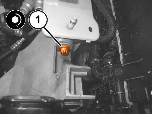
- 1. Tighten the NEW
front bolts (1) fixing the front suspension crossmember to the body, to the proper specification. Refer to TECHNICAL SPECIFICATIONS
.
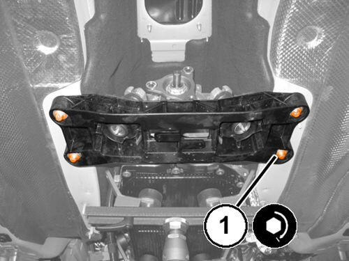
- Install the NEW bolts securing the transmission crossmember to the body and tighten to the proper specification. Refer to TECHNICAL SPECIFICATIONS .
- Remove the (special tool #BX50-CHR, Table, Bishamon Lift) complete with rubber spacer blocks such as ROTFJ2427/J2440 or equivalent supporting the powertrain assembly.
- Remove the hydraulic lift from underneath the differential.
- Install the ground lead in position and securely tighten the nut.
- Connect the automatic transmission wiring harness connector and secure it appropriately to the gearbox unit.
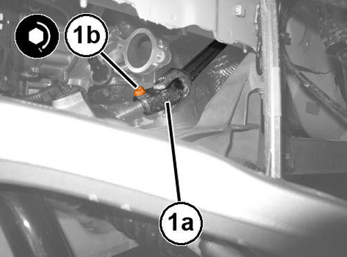
- Install the intermediate shaft (1a) to the steering gear and tighten the NEW bolt (1b) to the proper specification. Refer to TECHNICAL SPECIFICATIONS .
- Connect the quick connectors for the vacuum pipes.
- Connect the Powertrain Control Module (PCM) wire harness connector.
- Connect the quick connectors for the heater water supply and return pipes.
- Connect the front engine junction wire harness connector.
- Connect the PCM wire harness connector (Master).
- Install the body reinforcement in its seat and securely tighten the bolts to the body.
- Connect the engine front coupling.
- Connect the starter supply lead and securely tighten the nut to the terminal block.
- Place the terminal block protection back in its seat.
- Engage the body wiring retaining clips.NOTE:
Only use seal washers with an elastomer part in HNBR, resistant to R1234YF refrigerant.
NOTE:The use of seal washers with another elastomer material may increase the risk of serious leaks of refrigerant from the air conditioning system.
- Replace the connector O-rings.
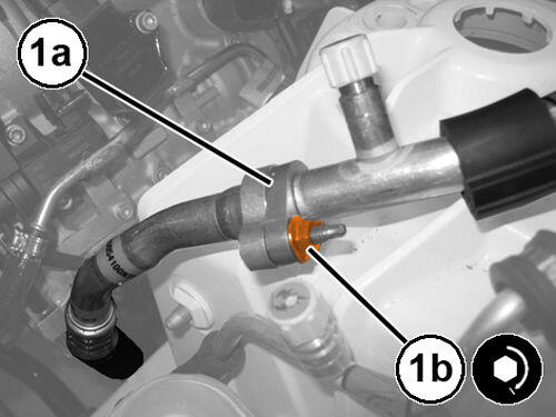
- Connect the intermediate connector (1a) on the line from the expansion valve to the air conditioning system compressor and tighten the nut (1b) to the proper specification. Refer to TECHNICAL SPECIFICATIONS
.
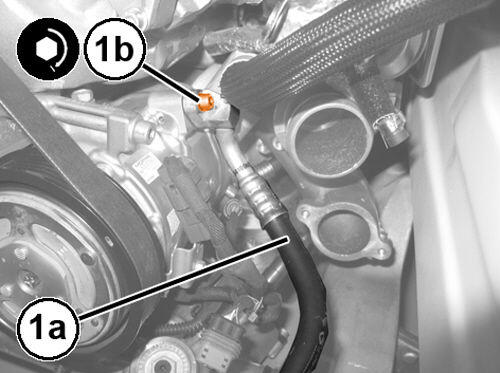
- Refit the engine coolant line (1a) to the air conditioning system compressor condenser, complete with NEW O-rings, and tighten the screw (1b) to the proper specification. Refer to TECHNICAL SPECIFICATIONS .
- Engage the retaining clip for the air conditioning system compressor condenser line.
- Connect the quick connector of the coolant return pipe to the supercharger air cooling system additional radiator.
- Connect the engine cooling system supply pipe rapid connector.
- Connect the quick connector of the coolant outlet pipe to the additional engine coolant radiator.
- Connect the quick connector of the coolant supply pipe to the additional engine coolant radiator.
- Connect the quick connector of the supercharger air cooling system feed pipe.
- Install the cowl panel cover. Refer to COVER, COWL PANEL, REMOVAL AND INSTALLATION .
- Install the front fuel delivery line. Refer to LINES, FUEL, REMOVAL AND INSTALLATION .
- Install the charge air water cooler support bracket. Refer to COOLER AND HOSES, CHARGE AIR, REMOVAL AND INSTALLATION .
- Install the left fuel vapor line between fuel vapor solenoid and the intake manifold. Refer to LINES, FUEL VAPOR, REMOVAL AND INSTALLATION .
- Install the right fuel vapor line between fuel vapor solenoid and the intake manifold. Refer to LINES, FUEL VAPOR, REMOVAL AND INSTALLATION .
- Install the front fuel vapor line. Refer to LINES, FUEL VAPOR, REMOVAL AND INSTALLATION .
- Install the right and left front struts. Refer to STRUT, SUSPENSION, ASSEMBLY, REMOVAL AND INSTALLATION .
- Install the right and left steering knuckle. Refer to KNUCKLE, STEERING, REMOVAL AND INSTALLATION .
- Install the propeller shaft. Refer to REMOVAL AND INSTALLATION .
- Install the front exhaust heat shield. Refer to SHIELD, HEAT, REMOVAL AND INSTALLATION .
- Install the fuel tank heat shield. Refer to SHIELD, HEAT, REMOVAL AND INSTALLATION .
- Install the exhaust muffler. Refer to MUFFLER, EXHAUST, REMOVAL AND INSTALLATION .
- Install the exhaust resonator. Refer to RESONATOR, EXHAUST, REMOVAL AND INSTALLATION .
- Install the right side catalytic converter. Refer to CONVERTER, CATALYTIC, REMOVAL AND INSTALLATION .
- Install the left side catalytic converter. Refer to CONVERTER, CATALYTIC, REMOVAL AND INSTALLATION .
- Install the air dam front crossmember. Refer to AIR DAM, FRONT, REMOVAL AND INSTALLATIONAIR DAM, FRONT CROSSMEMBER, REMOVAL AND INSTALLATION .
- Install the radiator. Refer to RADIATOR, ENGINE COOLING, REMOVAL AND INSTALLATION .
- Install the front spoiler actuator. Refer to AIR DAM, FRONT, REMOVAL AND INSTALLATIONAIR DAM, FRONT CROSSMEMBER, REMOVAL AND INSTALLATION .
- Install the hood. Refer to HOOD, REMOVAL AND INSTALLATION .
- Connect the negative battery cable.
- Fill the turbocharger cooling system. Refer to DRAINING AND FILLING THE TURBOCHARGER COOLING SYSTEM .
- Fill the engine cooling system. Refer to DRAINING AND FILLING THE ENGINE COOLING SYSTEM .
- Evacuate and charge the A/C system. Refer to PLUMBING, STANDARD PROCEDURE .
- Bleed the brake system. Refer to STANDARD PROCEDURE .